
")
Torpedo calculating discs
The location of the torpedo director at a different location than the torpedo tube resulted in the separation of deflection angle calculating and the aiming function. In the case of surface vessels, the usual torpedo aiming devices, which were set to the deflection angles received from the command station, were installed at the torpedo tubes. The calculating devices, called director angle calculating discs (Germ. Torpedorechenscheibe) which solved the torpedo triangle were located at the command stations. In the case of submarines, during surfaced attacks, the common torpedo director located on the bridge was used. During submerged attack, the aiming was done by periscope, while the deflection angle was calculated in the control room by means of torpedo calculating discs or tables.
The torpedo calculating disc utilized the torpedo triangle theory based on two known variables: angle on the bow and target speed to determine the torpedo deflection angle. Additionally, torpedo calculating discs could have scales which determined (for the assumed angle on the bow and target speed) the maximal distance to the target at the moment of torpedo launch, for the target to be in range of the torpedo.

Drawing 1. Replica of a German torpedo calculating disc
The disc consists of a circular dial with a scale (from 0 to 180º port and starboard) on its edge which represents the target angle on the bow. It is also used for reading the deflection angle. The dial contains parallel lines that represent the target bearing. These line are inside the smaller circle and connect respective values of the angle on this circle, i.e.: 10º and 170º, 20º and 160º, 30º and 150º and so on.
Over the dial is the lineal, which can be rotated around the center. On this lineal is a scale for setting target speed – in the range of 6 to 30 knots.
To calculate deflection angle, the lineal has to be rotated so that its edge (crossing the dial center) indicates the angle on the bow on the outer dial scale. Then the target bearing, which crosses the lineal against the respective target speed has to be read. The angle which corresponds to the target bearing is the deflection angle.
There are arcs drawn on the dial that are the parts of circles which have the same radius as the circle which encloses the target bearing lines, but their centers are shifted. Each arc is described by a number that represents the distance to the target at the moment of torpedo launch.
To determine the maximum distance to the target (for the assumed angle on the bow and target speed), the arch which crosses the lineal against the respective target speed (interpolating if necessary) is used.
The scales of the presented calculating disc are correct for torpedoes running at a speed of 30 knots and a maximum range of 12500 meters (data for the G7a torpedo). In the case of other torpedoes, the scales have to be altered.
The operating principle of the torpedo calculating disc is as follows: the torpedo triangle is constructed in such way that point A represents the ship launching the torpedo, point B represents the target at the moment of torpedo launch, and point C is the point where the torpedo will intersect (hit) the target. The length of the triangle side AC is equal to the length of torpedo speed vector (that is at 30 knots) – it is also equal to the radius of the circle, on which are located points A and D. The target speed scale on the lineal is at the same scale as the torpedo speed – with the value 0 at the center of the dial. The length of triangle side BC is equal to the target speed vector. Side AB is parallel to the circle diameter which connects the points representing bearings 0 and 180º.
The angle on the bow γ between triangle sides AB and BC is equal to the angle between side BC and the circle diameter which connects the points representing bearings 0 and 180º, so the angle on the bow can be easily set by aligning the lineal to the corresponding position on the dial’s outer scale.
The deflection angle β between sides AC and AB is the same as the angle between sides AD and CD, equal to the angle between side CD and the circle diameter which connects the points representing bearings 0 and 180º. So the deflection angle can be easily read from the dial’s outer scale (to make this easier, the target bearing lines are described).

Drawing 2. Torpedo calculating disc operating principle
Determining the maximum distance to the target at the moment of the torpedo launch works on the following principle: the radius of the circle, on which points A and D are located, corresponds (in some scale) to the maximum range of the torpedo (that is 12500 meters for G7a torpedo). There are arcs on the dial that are parts of circles of the same diameter with their centers shifted down (in the same scale) in increments of 2500 meters. Point A is located on the circle “0”, and point B – near the circle “7”. So points A and B – located on the same bearing line (which is parallel to the line which connects the centers of the shifted circles) are the same distance apart as the centers of respective circles – “0” and “7” – that is about 7 * 2500 meters = 17500 meters. So, if at the moment of the torpedo launch the target is at a distance less than 17500 meters, a torpedo with a maximum range of 12500 meters reaches the target.
Demonstration showing the operation of such calculating disc is available here.
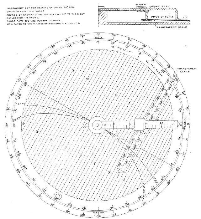
Drawing 3. British torpedo calculating disc from World War I
(Torpedo Control Disc Mark I) [1]
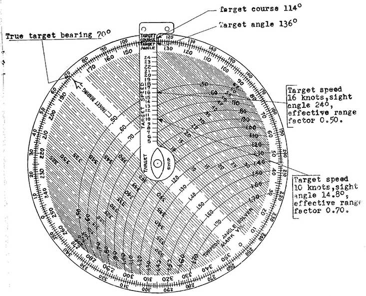
Drawing 4. American torpedo calculating disc from World War II
(Torpedo Angle Solver Mark 7) [2]
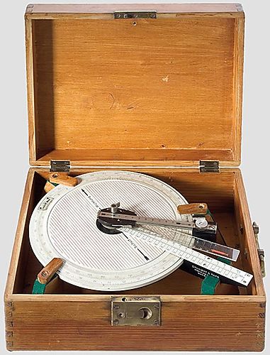
Photo 1. German torpedo calculating disc manufactured by Dennert & Pape Company in Hamburg [3]
For the British and German calculating discs above the principle of determining maximum (allowable) distance to the target is quite different than described before. These discs do not have arcs representing distances. The dials have additional transparent lineals instead, which can be shifted and rotated along the target speed lineal. This lineal is scaled so, that the radius of the dial corresponds to the maximum torpedo range. When the target speed lineal is set correctly, the additional range lineal is shifted to the point corresponding to the target speed and rotated to be parallel to the bearing lines on the dials. The measured distance between the target speed lineal and the dial edge corresponds to the maximal distance (allowable) to the target at the moment of torpedo launch.

Photo 2. German torpedo calculating disc manufactured by Dennert & Pape Company in Hamburg [4]
References:
[1] Handbook of Torpedo Control, 1916, ADM 186/381
[2] Torpedo Angle Solver Mark 7 and Mods.
[3] Subsim - an other KM wizz-wheel model?
[4] Treffpunktrechner - Dennert&Pape Whiz Wheel