
")
Torpedo fire control system and Fat torpedoes
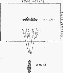
On 22 August 1941, BdU (Befehlshaber der U-Boote, U-Boat High Command) directed a query to TVA (Torpedoversuchsanstalt, Torpedo Experimental Station), if G7a (T I) wet-heater torpedo could be modified in such way that after travelling the pre-set distance, it would start to circle with diameter of 1000 – 1500 meters. This query resulted from the idea that in the case when torpedo missed the target in convoy, the remaining torpedo run could be utilized to circle (inside the convoy), thus creating the another chance for hit. For instance, the G7a wet-heater torpedo with the maximum running distance of 12500 meters (at 30 knots), launched to the target 1000 meters away, after missing, run for another 10 km. If it started to circle (after missing the target) with diameter of 1000 – 1500 meters, it would make 3 – 2 rounds before exhausting the fuel, crossing the courses of the other ships in convoy.
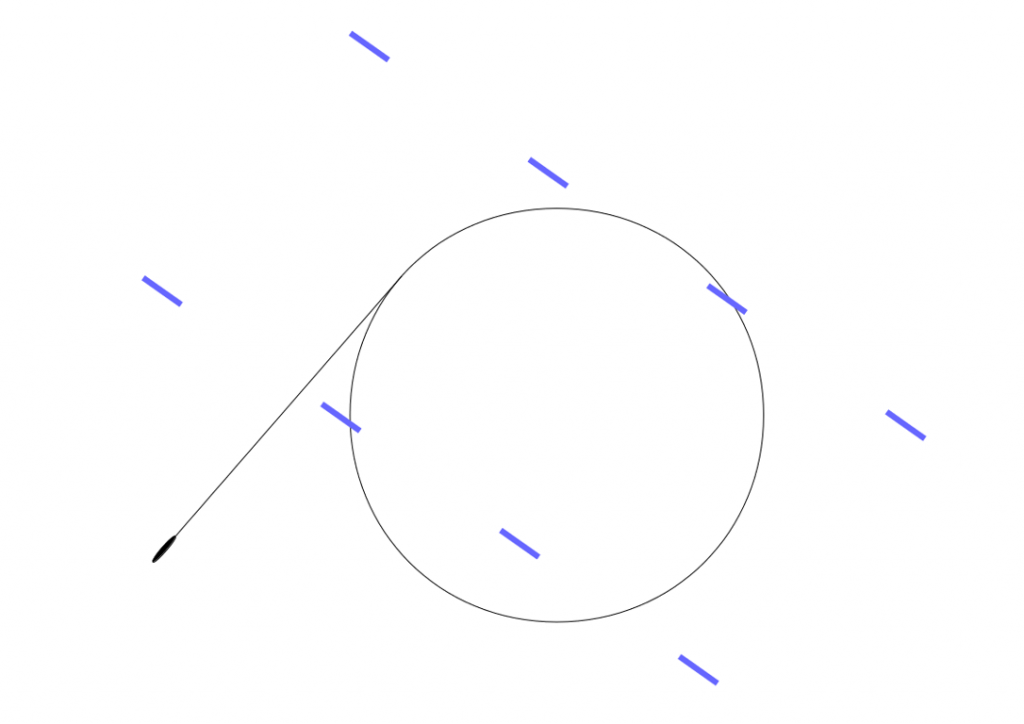
Drawing 1. The BdU idea of the circling torpedo
The drawing presents the track of the torpedo that after travelling distance of 1000 meters starts to circle with diameter of 1200 meters. The blue dashes represents the ships in convoy (length of the ship 130 meters, distance between ships in the column 500 meters, distance between columns 1000 meters).
The initial assessment stated that such modification was feasible, so on 25 November 1941 it was decided to start development of such control device for T I wet-heater and T II electric torpedoes. The control device was temporarily designated as "K-Einrichtung" (Kurvensteuerung-Einrichtung).
The theoretical researches proved that only small fragments of the track of the torpedo circling with so large diameter provide the correct impact angle, assuring the proper operation of the impact pistol (i.e. in range of 30 – 150°) and that the convoy quickly leaves the danger zone created by circling torpedo. Moreover, the rudder deflection required to make turn of so large diameter (above 500 meters) was only 0.7-3.5° (depending on torpedo speed). The torpedo track deviated from the circle because it was impossible to precisely control so small rudder deflection.
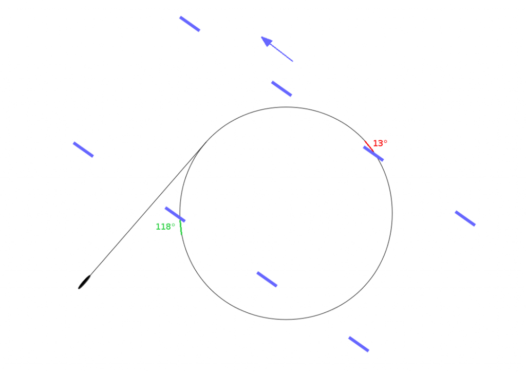
Drawing 2. Impact angles of the torpedo circling with diameter of 1200 meters
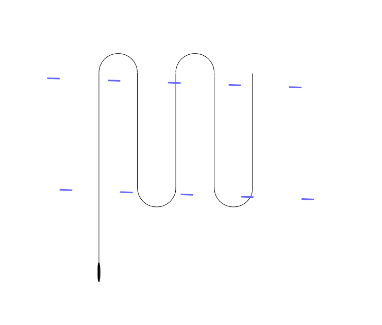
Therefore, aside from the circular run (Kreisläufer) proposed by BdU, TVA considered the loop run (Schleifenläufer), spiral run (Spiralenläufer) and zigzag/saw run (Sägenläufer).

Drawing 3. Loop (Schleifenläufer), sipral (Spiralenläufer) and zigzag (Sägenläufer) torpedo run
Finally, the loop run was selected for further development. The torpedo track had a shape of lengthen loops which moved along the convoy course, so longer fragments of the torpedo tracks provided required impact angle.
Drawing 4. Loop running torpedo and the convoy
The blue dashes represents the ships in convoy (length of the ship 130 meters, distance between ships in the column 500 meters, distance between columns 1000 meters).
The spiral run was rejected due to constructional difficulties and small chances for success. The zigzag run was designated for future development (later implemented as Lut torpedoes)
On the beginning of December 1941 the following requirements of the loop run were defined: two selectable lengths of the loop (kurz and lang, 1190 meters and 1840 meters for G7a torpedoes and 1050 meters and 1750 meters for G7e torpedoes), pre-set length of the preliminary straight run and turn radius equal to 170 – 250 meters (required rudder deflection was 6 - 7°).
According to the schedule, 12 G7a wet-heaters torpedoes were to be converted to the experimental pattern-running models in January 1942, while in April and June 1942, hundreds of pattern-running G7a and G7e torpedoes were to be combat ready.
The development and testing of the control device was conducted by TVA department in Gotenhafen-Oxhöft (Gdynia-Oksywie). This department, based on experience gained while developing electrically controlled gyro GA VIIIs “Specht” for homing torpedoes, developed pneumo-mechanical control gear. The torpedoes fitted with this gear were designated as Fat (Federapparattorpedo, often mistakenly expanded as Flächen-Absuch-Torpedo) and were marked with green strips painted on the torpedo rudder.
The development was delayed so refined version of the pattern-running G7a wet-heater torpedo was ready only on the beginning of October.
The final version of the control gear allowed for:
- selection of the direction of the pattern (relatively to their initial course) – left or right (links, rechts)
- selection of the loop length: long or short (lang, kurz, of length ~1900 meters and ~1200 meters)
- setting the length of the preliminary straight run (Vorlauf) in range from 150 meters to 15 km.
The turn radius was equal to 170 meters.
The Fat control gear consisted of type GA VIII gyro (built-in straight running wet-heater T I torpedoes and electric T II torpedoes) and Fat pattern gear.
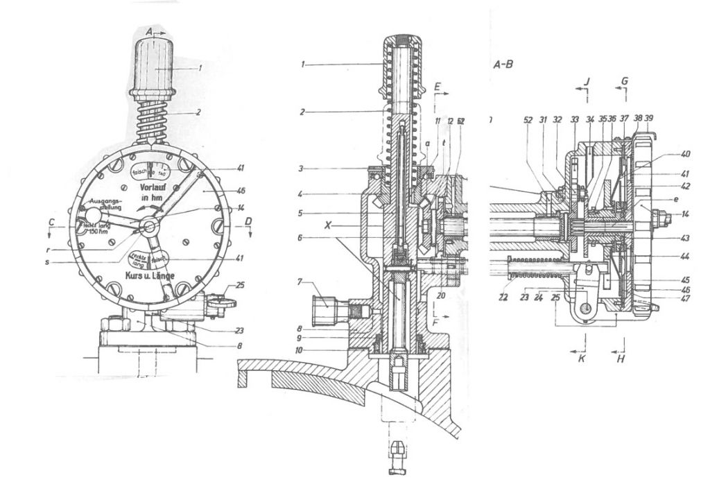
Drawing 5. Fat control gear
(type GA VIII gyro to the right, pattern gear to the left) [1]
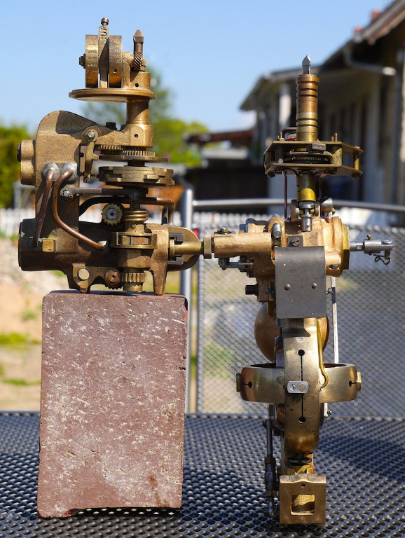
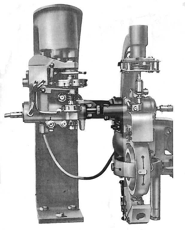
Photo 1. Fat control gear
(type GA VIII gyro to the right, pattern gear to the left)
When the torpedo left the tube, it turned by pre-set angle (so called gyro angle, Germ. Schußwinkel) and then run straight. Both turn and straight run was controlled by type GA VIII gyro. The spinning gyro disc determined the fixed reference plane in space (this plane was perpendicular to the longitudinal axis of the torpedo tube). The gyro angle was set relative to this reference plane. The gimbals were coupled with pneumatic steering-engine which actuated the rudder of the torpedo. The gyro angle was set by rotation of the setting spindle (Germ. W-Einstellspindel), which was located at the aft part of the torpedo hull, at right side (one turn of the setting spindle was equal to the 2° of gyro angle).
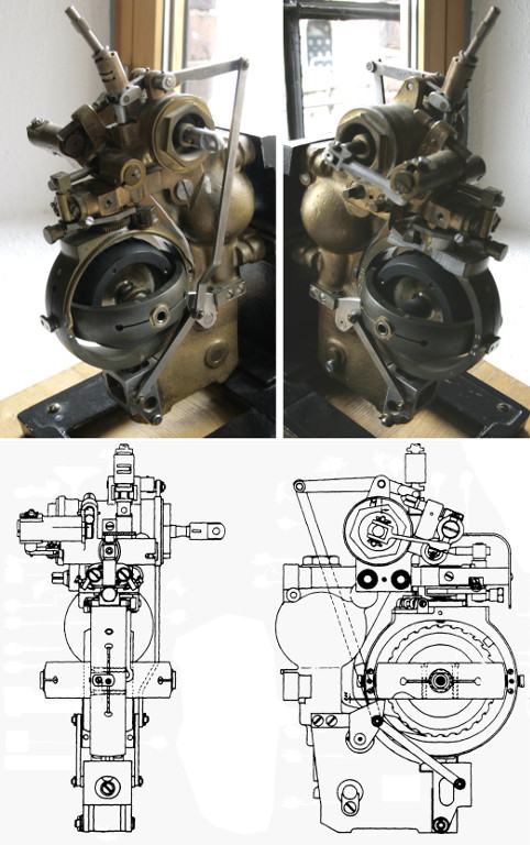
Photo 2. Type GA VIII gyro

Photo 3. The gyro angle setting spindle
(loading the G7e electric torpedo into the aft torpedo room of the type IX U-Boat)
The Fat pattern gear consisted of several cams: the cam controlling the length of the preliminary straight run (Vorlaufscheibe), the set of four steering cams controlling the pattern (Steuerscheibe rechts kurz, links kurz, rechts lang, links lang) and the setting cam (Nockenscheibe), used for selecting one of four steering cams.
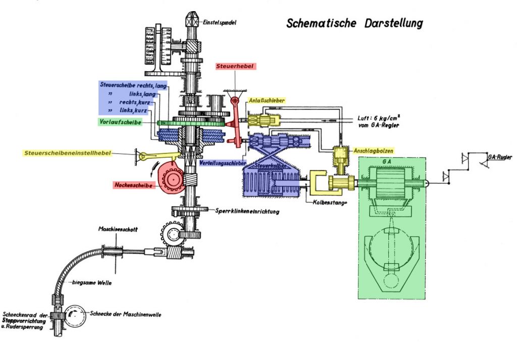
Drawing 6. Fat pattern gear [1]
| Steuerscheibe rechts, lang | the steering cam, pattern rechts, lang |
| Steuerscheibe links, lang | the steering cam, pattern links, lang |
| Steuerscheibe rechts, kurz | the steering cam, pattern rechts, kurz |
| Steuerscheibe links, kurz | the steering cam, pattern links, kurz |
| Vorlaufscheibe | the cam for controlling the length of the preliminary straight run |
| Nockenscheibe | the setting cam |
| Steuerscheibeneinstellhebel | the setting cam follower |
| Steuerhebel | the steering cam follower |
| Anlaßschieber | the starting valve |
| Verteilungsschieber | the control valve of the Fat steering engine |
| Steuerkolben | the control piston of the Fat steering engine |
| GA | the steering engine of the GA gyro |
| Kolbenstange | the steering engine linkage |
| Anschlagbolzen | the pneumatically controlled coupling |
| GA-Ruder | the torpedo rudder |
| Einstelspindel | Fat setting spindle |
| Luft: 6 kg/cm2 vom GA-Regler | the compressed air (6 kg/cm2) supply from the gyro reducing valve |
| Sperrklinkeneinrichtung | the unidirectional clutch |
| Maschinenschott | the bulkhead between engine compartment and aft compartment |
| biegsame Welle | the flexible drive shaft |
| Schneckenrad der Stoppvorrichtung u. Rudersperrung | the worm wheel of the engine stoping gear and depth rudder locking gear |
| Schnecke der Maschinenwelle | the worm at the drive shaft |
The lateral surface of the setting cam was divided into four parts, which corresponded to the four maneuvering patterns. The setting cam follower (Steuerscheibeneinstellhebel) slid the set of four steering cams into the one of four positions. In each position only one steering cam had a contact with the steering cam follower (Steuerhebel). The steering cam follower was actuated by currently selected steering cam. The follower was coupled with the pneumatic steering engine (Verteilungsschieber + Steuerkolben), which in turn, by means of the pneumatically controlled coupling (Anschlagbolzen), was coupled with pneumatic steering engine of the gyro (GA). The steering cam had a rounded shape with two pairs of indentations and two pairs of notches for rechts lang and links lang cams, and three indentations and three notches for rechts kurz and links kurz cams. The indentation forced the right turn, while the notch the left run.
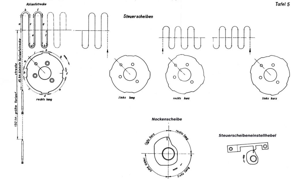
Drawing 7. The steering cams, maneuvering patterns and setting cam [1]
| Steuerscheiben | the steering cams |
| Ablaufstrecke | torpedo track |
| Nockenscheibe | the setting cam |
| Steuerscheibeneinstellhebel | the setting cam follower |
| 150 hm; größte Vorlaufstrecke | 150 hm; the greatest length of the preliminary straight run |
| 1,5 hm; kleinste Vorlaufstrecke | 1,5 hm; the smallest length of the preliminary straight run |
The steering cam follower was actuated by preliminary straight run cam. The lateral surface of this cam was divided into two parts (of the same length). The first part controlled the straight run, while the second part controlled the pattern running. During the first stage of run (preliminary straight run) of the torpedo, the preliminary straight run cam kept the steering cam follower away from the steering cam. The length of the preliminary straight run depended on the initial position of the cam. When the cam was trained sufficiently, it allowed the steering cam follower to get in contact with the steering cam. Additionally, the steering cam follower opened the starting valve (Anlaßschieber), enabling the pneumatically controlled coupling (Anschlagbolzen), hereby establishing the mechanical connection between Fat steering engine and gyro steering engine. The starting valve also supplied the compressed air to the Fat steering engine (which was necessary for operation the steering engine).
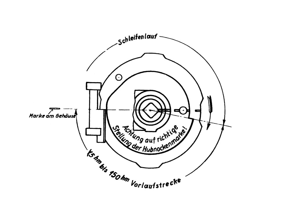
Drawing 8. The preliminary straight run cam [1]
| Schleifenlauf | pattern running |
| Marke am Gehäuse | the mark at the housing |
| 1,5 hm bis 150 hm Vorlaufstrecke | preliminary straight run length in range 1,5 hm to 150 hm |
| Achtung auf richtige Stellung der Hubnockenmarke! | watch out for the proper position of the cam mark! |
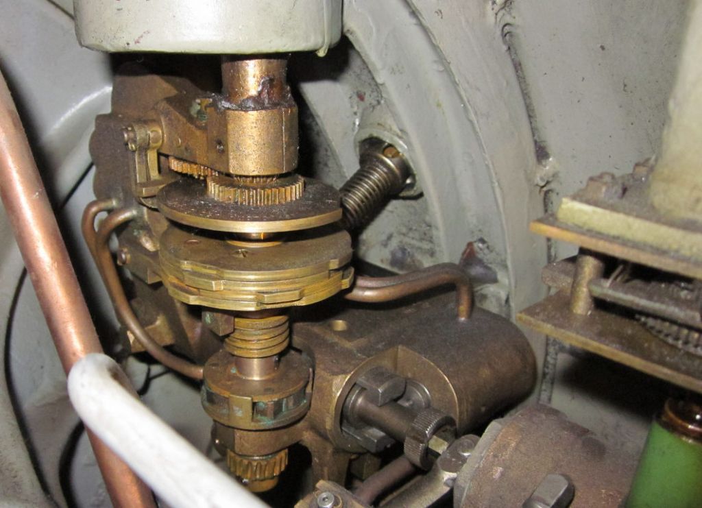
Photo 4. The Fat pattern gear of the G7a (T I) wet-heater torpedo
The length of the preliminary straight run (Vorlauf) and pattern mode (Schleifenlauf) was set by means of the single setting spindle (Germ. Fat-Einstellspindel), which was located just in front of the gyro angle setting spindle (Germ. W-Einstellspindel).
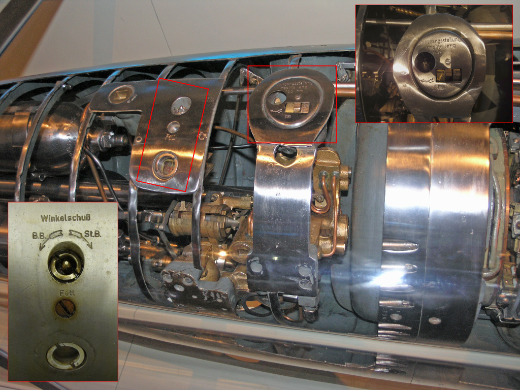
Photo 5. The Fat setting spindle and gyro angle setting spindle of the G7e electric torpedo in the MSI, Chicago
The Fat setting spindle rotated (by means of the gear of ratio 4:1) the preliminary straight run cam and at the same time (by means of the worm gear of ratio 16:1) the setting cam. Since only the half of the Vorlaufscheibe was designated for controlling the preliminary straight run, to set the correct value, the spindle could be rotated only so much as two turns. In the same time the setting cam would rotate only so much as 1/8 turn. Because the setting cam is divided into four parts (corresponding to the four steering cams), the current steering cam would not change (the cam would turn only so much as half of the quarter of the cam). Only after the next two turns of the spindle, when the Vorlaufscheibe was trained into its initial position, the setting cam turned by the following 1/8 turn (i.e. the second half of the quarter of the cam), moving the set of steering cams into the next position (enabling the next steering cam).
In other words, the first two turns of the setting spindle set the preliminary straight run length for the first maneuvering pattern, after next two turns the steering cam is changed and the length of the preliminary straight run can be set for the currently selected steering cam, and so on.
The dedicated setting device (Germ. Fat-Stellzeug) attached to the torpedo tube was used to make correct setting of the length of the preliminary straight run and pattern mode of the torpedo loaded into the tube.
Drawing 9. Fat setting gear [1]
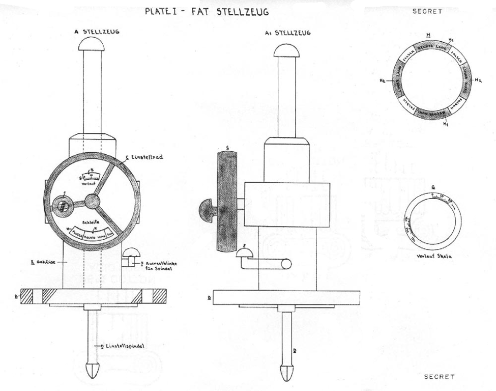
Drawing 10. The drawing of the Fat setting gear made during the interrogation of the survivors from U 664 [2]
The Fat setting gear consisted of the hand-wheel, two coaxial discs (one of them presents the length of the preliminary straight run, while the other the current maneuvering pattern) and the handle (when pressed, the Fat setting spindle was retracted into the tube and torpedo). If any of the discs showed Falsch label, the setting was invalid. The Falsch label at the external disc (showing the length of the preliminary straight run) corresponded to the part of the Vorlaufscheibe, which allowed for the contact of the steering cam follower with the steering cam. The Falsch label at the internal disc (showing the maneuvering pattern) corresponded to the second halves of each quarter of the setting cam. Leaving the setting cam in such position meant that during torpedo run, the setting cam turned into the position corresponding to the next steering cam. That meant undesired change of the maneuvering pattern during the torpedo run. The hand-wheel could be trained only counter clockwise, so when the desired setting was missed, it was necessary to train the hand-wheel by 16 turns to set it again.
When the torpedo was launched, the cams where turned (by means of the flexible driving shaft) by forward end of the engine shaft (through the unidirectional clutch, so while the cams were trained by the Fat setting gear, the engine shaft was still). The engine shaft revolutions corresponded to the distance traveled by torpedo (similarly as in case of the stop and rudder locking gear, Germ. Stoppvorrichtung und Rudersperrung).
As one can see, the Fat pattern gear had nothing to do with spring gear, as the German name Federapparattorpedo suggests. Most likely, the name comes from the first version of the pattern gear, which based on the clockwork (Germ. Federwerk).
The extensive trials were conducted on 2 October 1942 by TVA and TEK (Torpedoerprobungskommando, Torpedo Trials Department) with complicity of 25th U-Boat Training Flotilla in Gdańsk Bay (Germ. Danziger Bucht). The exercise convoy attacks conducted by U 268 in presence of BdU Karl Dönitz, BdU deputy (2. Admiral der Unterseeboote) von Friedeburg, Chief of the Torpedo Office (Amt Torpedowaffe) Vice-Admiral Otto Backenköhler and Chief of the TI (Torpedoinspektion, Torpedo Inspection) Admiral Otto Ciliax, proved effectiveness of the new weapon. BdU found the Fat torpedo ready to combat usage and ordered to enter it to the service as fast as possible.
Because the visible wake of the G7a wet-heater torpedo (the bubbles of the exhaust gases) could betray the maneuvering feature of the Fat torpedo, to keep it in secret as long as possible (and to prevent any counteraction), it was ordered to use it at night only.
In order to use Fat torpedo effectively, the length of the preliminary straight run (Vorlauf) had to be set properly. If length was too long or too short, the torpedo started to maneuver behind and in front of the convoy respectively, being completely useless.
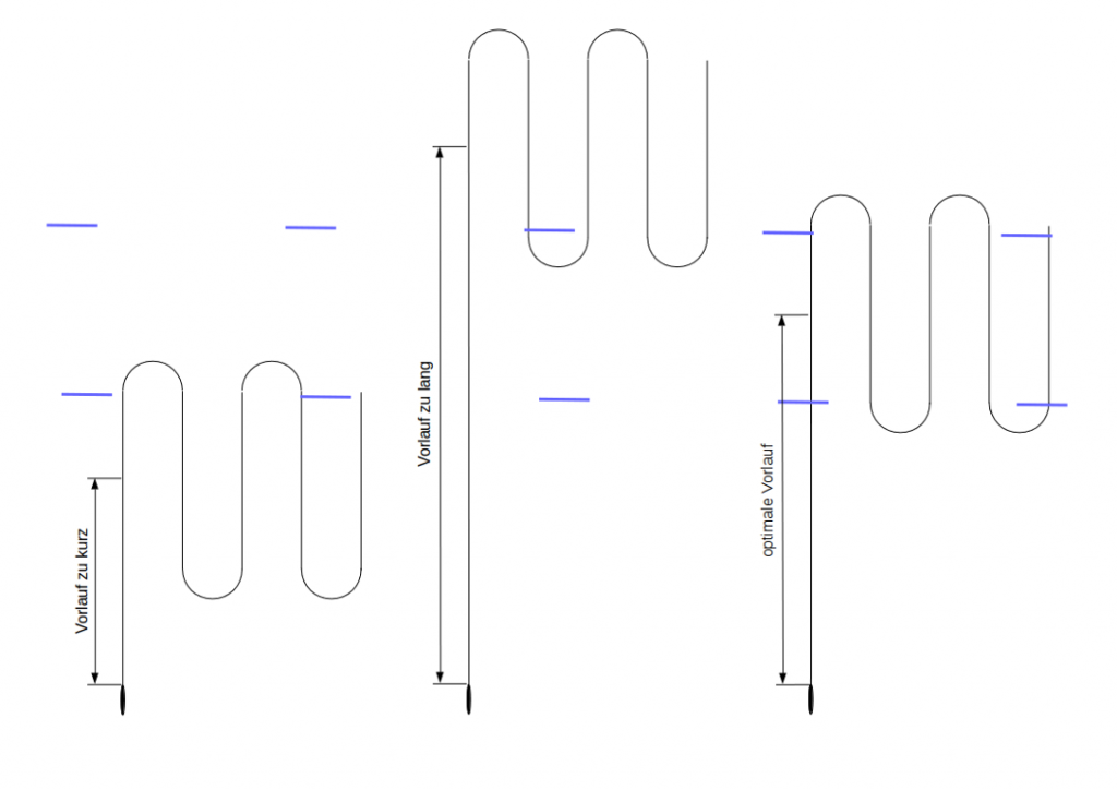
Drawing 11. Too short, too long and optimal length of the preliminary straight run (Vorlauf)
On 19 October 1942, BdU and MND (Marinenachrichtendienst, Naval Intelligence Office, supervising the research, development and manufacture of the radar equipment for Kriegsmarine) decided to arm with Fat torpedoes the U-Boats that were equipped with the new type FuMO 30 radar set. Owing to the radar, during the convoy attack, the accurate distance to target in the moment of torpedo launch (Schußentfernung) could be measured, which later should be (for instance by means of the torpedo calculator) converted to the length of the preliminary straight run (Vorlauf). The first U-Boats were to be ready to service in the mid-November 1942, however due to shortage of the radar sets, the installation works lasted until the end of December 1942. Because of this delay, for about 1 month, 10 combat ready U-Boats stayed in yards instead of North Atlantic. According to BdU, this resulted in the decreasing of the sinking ratio in the end of 1942.
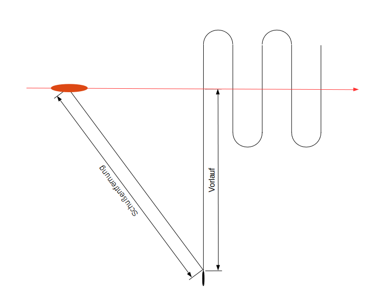
Drawing 12. Distance to the target (Schußentfernung) and length of the preliminary straight run (Vorlauf)
On 8 November 1942, BdU foreseeing (based on the intelligence) large convoy operation in the West Mediterranean, ordered to arm with Fat torpedoes the U-Boats operating in Mediterranean (indeed, it was the allied operation Torch). The 24 Fat torpedoes stored in Kiel were to be transferred to Mediterranean bases of the 29th U-Boat Flotilla: 6 torpedoes to Pola (at that time in Italy, nowadays in Croatia) and 18 torpedoes to La Spezia (Italy).
The shipyards technicians had to be sent there from Kiel, who were to adjust the torpedo tubes to the new type of torpedo. In practice it was required to drill one hole in the tube and install the Fat setting gear. Due to lack of time (and limited number of torpedoes), only two torpedo tubes of four U-Boats (U 83, U 373, U 453 i U 562) were to be modified. Each U-Boat was to carry six Fat torpedoes. The schedule was as follows:
| U 375 | Pola | 17.11.1942 |
| U 562 | La Spezia | 22.11.1942 |
| U 453 | La Spezia | 28.11.1942 |
| U 83 | La Spezia | 29.11.1942 |
This schedule was not executed. Perhaps BdU realized that few Mediterranean U-Boats armed with new torpedoes in the end of November did not influence on Torch operation (after seizing harbors in Morocco and Algeria on 8 November, regular supply convoys to Africa were established: UGF and UFS from USA to Gibraltar, KMF and KMS from UK to Mediterranean). Anyway, based on analysis of U-Boats War Diares one can say that none of these four U-Boats was fitted with Fat torpedoes until the end of 1942.
Of the Mediterranean U-Boats, the first U-Boat armed with Fat torpedoes was U 73 in La Spezia, just before her 10th war patrol (which began on 1 December). However, they were used (most likely) on her next patrol, during an unsuccessful attack on convoy, on 26 December 1942.
The BdU War Diary contains an entry (on 29 November 1942) saying that the first Atlantic U-Boat on war patrol with Fat torpedoes was U 533. This boat left St. Nazaire on her 9th war patrol on 23 November. On 9 December the U-Boat attacked convoy HX-217, launching two salvos (2 torpedoes each). Among the launched torpedoes could be Fat type. The first salvo hit and sunk British motor merchant Charles L.D.
On 14 December 1942 U 406 left St. Nazaire for her 4th war patrol. At night 28/29 December 1942, during the attack on convoy ONS-154 five torpedoes were launched (including two Fat torpedoes), which hit and damaged British steamers Baron Cochrane, Lynton Grange and Zarian.
The survivors from U 662 (sunk on 21 July 1943) testified that at night 28/29 December 1942 during the attack on the same convoy ONS-154 the salvo of two Fat torpedoes were launched. The salvo missed the target. It was their 2nd war patrol, which begun on 19 December 1942 in Lorient.
Because of the delays in arming the U-Boats with Fat torpedoes resulting from the deficiency of the radar sets, on 8 January 1943 BdU ordered to arm with Fat torpedoes as many U-Boats as possible, irrespective from available radar sets. During the operation of U 406 against the convoy ONS-154 the distance to the target was estimated by eye, which appeared to be accurate enough conduct successful attack with Fat torpedoes (wherein BdU sensitize the commanders that it was better to overestimate the distance than underestimate).
At the same time, the usage of the Fat torpedoes at Mediterranean was prohibited due to operational difficulties (the torpedo wake was visible even at night because of water clarity and high phosphorescence). The Fat torpedoes were allowed for usage on the Northern Waters (Norwegian Sea, Barents Sea and Kara Sea) instead. On May 1943 the usage of Fat torpedoes on the Northern Waters was cancelled, because of the Midnight Sun, lasting from the end of April till the end of the August. During that time the torpedo wake was visible around the clock. It was planned to allow usage of the torpedoes again, when the Midnight Sun ended.
So since May 1943 the Fat torpedoes were operationally used only on Atlantic.
The Fat torpedoes launched toward the convoy, endangered not only the ships but also other U-Boats attacking the same convoy within the wolfpack. The most endangered were U-Boats inside the convoy. Therefore, the U-Boat that intended to attack with Fat torpedoes was obligated to transmit a special radio message, so called "Fat warning" (Germ. Fat Warnung) several minutes before the attack. The warning was valid for 30 minutes. After receiving such warning, the U-Boats inside the convoy had to run away or to dive to depth at least 50 meters.
Midshipman Hans-Jürgen Zupke (who in 1943 passed the dedicated training of Fat torpedoes in Brest) testified that Fat warning was supplemented with the information about intended maneuvering pattern (Zupke was one of 9 survivors from U 439, which sunk on 4 May 1943 after collision with U 659, west to the cap Cabo Fisterra).
Besides the single shots, to enlarge the danger zone (and to increase the possibility of hitting) the salvo shots were used. The salvo could contain two, three or four Fat torpedoes. The general rule was to set the maneuvering pattern alternately: kurz and lang. Additionally, each torpedo in salvo could be set to slightly different length of the preliminary straight run.
Drawing 13. The Fat salvo, the drawing made during the interrogation of the survivors from U 664 [2]
The production rate of the Fat torpedoes was only 100 per month. The low rate resulted from the high labor intensity during manufacturing the G7a wet-heater torpedoes, manufactured at rate 350 per month. Some of them were intended for torpedo training at Baltic Sea while the others for torpedo boats. So only small number of the torpedoes could be modified to maneuvering version.
The pattern running type G7a Fat wet-heater torpedo could run only at speed of 30 knots (the speed setting WS – Weitschuss). At that speed the torpedo range was the largest (equal to 12 km). Moreover, the G7a torpedo turning with radius 170 m at speed greater than 30 knots did not keep depth properly. Therefore the development was continued to have the wet-heater torpedo able to maneuver with speed of 40 knots (the speed setting NS – Nahschuss). Finally, the results were not satisfying and only 30 knots version of the Fat torpedo was used in action.
At the same time, while working on the pattern running wet-heater torpedo, the maneuvering version of electric torpedo G7e was in development. As far as the Fat pattern gear created for wet-heater torpedo could be used in electric torpedo (which was fitted with the same gyro control system), the main problem was its small range, only 3 km (5 km after heating the torpedo battery up to 30° C).
The type T II electric torpedo was driven by electric motor powered by the type 13 T 210 acid-lead battery, manufactured by Accumulatoren-Fabrik (AFA). The battery consisted of two ebonite containers. Each container enclosed 26 cells connected in series. Each cell was built of 13 positive plates and 14 negative plates. The output voltage of each container was equal to 46 V. Two containers were connected in series, building the type 13 T 210 battery, of output voltage of 91 V, capacity of 85 Ah (93 Ah after heating up to 30°C) and weight of 665 kg. The torpedo powered by this battery could travel 3000 m (5000 m after heating up to 30°C) at speed 30 knots.
The combat ready type T II torpedo weighed 1606 kg, whereas its buoyancy was equal to 1306 kg, wherein the center of gravity was located about 40 cm behind the center of buoyancy (about 2 cm closer than in case of type T I torpedo). As the result of net forces, the submerged torpedo was turned around transverse axis (crossing the center of buoyancy), forcing the vertical position, with torpedo stern down.
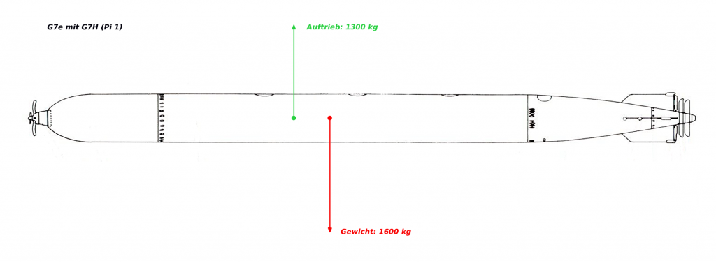
Drawing 14. The gravity and buoyancy forces acting on the type G7e (T II) electric torpedo
To counteract this rotation (and to keep horizontal orientation of the torpedo), the depth rudder had to be deflected slightly down (by the so called free angle, Germ. freie Winkel). The water flowing the depth rudder generated the hydrodynamic force, directed upward. This force lifted the stern of the torpedo, thus preventing the rotation of the torpedo to the vertical position. In other words, the torpedo cruising at preset depth had depth rudder deflected down by few degrees (rather than in horizontal position, as it would be in case of the torpedo, of which the center of gravity overlaps the center of buoyancy).
The type T II torpedo had negative buoyancy of 300 kg and as a result it sunk. To counteract the negative buoyancy, the hydrodynamic force generated by torpedo hull was used. For this purpose the torpedo had to cruise with stern slightly lower than the head, so the longitudinal axis was inclined to the horizon at the angle called attack angle (Germ. Anstellwinkel). This attack angle was gained by decreasing the free angle value corresponding to the horizontal orientation of the torpedo. The free angle was set by adjusting the length of the linkage between depth gear steering engine and depth rudders.
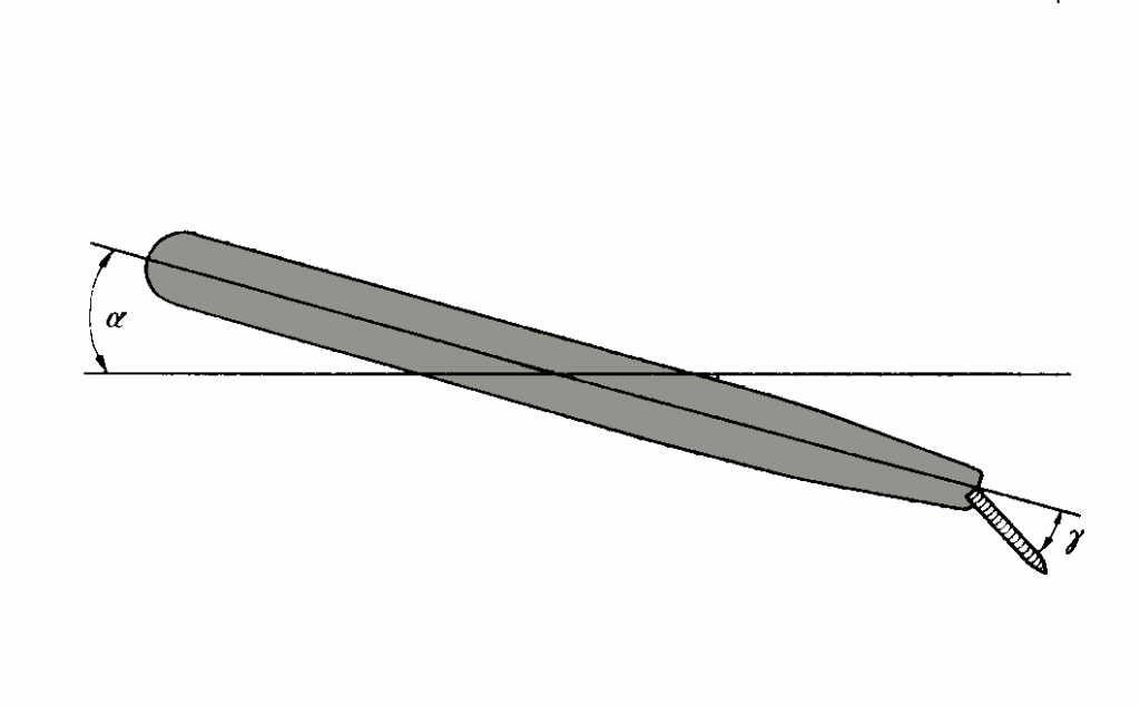
Drawing 15. The free angle γ and attack angle α [3]
In the end of 1941, as a solution of the type T II torpedo short range problem it was proposed that after traveling the preliminary straight run (i.e. just before beginning of pattern running), the two 26-cell containers of type 13 T 210 battery were switched from the serial to parallel connection. Thus the output voltage powering the motor dropped to 46 V, so the speed decreased down to 20 knots, however the capacity of the battery was doubled. As a result the remaining range of torpedo was tripled (for instance, when length of the preliminary straight run was set to 1000 meters, the remaining range was 12000 meters at speed 20 knots instead of 4000 meters at speed 30 knots). During the trials it appeared that in the moment of switching batteries, when the speed changed from 30 to 20 knots, the torpedo rapidly decreased the depth (the pendulum of the depth gear, due to inertia, was moved forward when speed decreased, which was the same result as the head moved down, so the depth gear steered the torpedo up). Moreover, the torpedo powered this way could not be armed with new influence pistol Pi 2 (which entered service in the end of 1942), because it required the powering by the battery with full output voltage of 91 V. Additionally, the torpedo cruising with lesser speed required greater attack angle (Anstellwinkel) to counteract the negative buoyancy. The trials proved that when the torpedo was cruising with greater attack angle, it started to heel oscillatory. The heeling appeared to be serious problem because it could cause leakage of battery electrolyte (if heel angle greater than 20°). Moreover, in the moment of hitting the target, the heeling of the torpedo increased the chance for failure of the type Pi G7a or Pi 1 impact pistol.
The heeling was removed by increasing the area of the vertical stabilizers. The size of the vertical stabilizers of previous types of torpedoes was restricted by internal diameter of the torpedo tubes (equal to 553 mm). To avoid this restriction, the extensible vertical stabilizers (Germ. ausschiebbare Flossen) were used. These were additional stabilizers, whose contour in the resting position (in which were held by springs) overlapped with actual vertical stabilizers. These additional stabilizers were extended by pneumatic pistons, supplied with compressed air (under pressure of 6-8 kg/cm2), from the gyro reducing valve (Regler für G A). In the moment of the torpedo launch, simultaneously with starting the motor, the main air valve was opened and enabled compressed air supply (by means of the gyro reducing valve) to the gyro, steering engines and pistons of the extensible vertical stabilizers. As soon as the torpedo cleared the tube, the pneumatic pistons extended the extensible stabilizers, increasing their lateral area by about 30%. The larger lateral area of the vertical stabilizers resulted in heeling extinction and increased the stability of the torpedo.
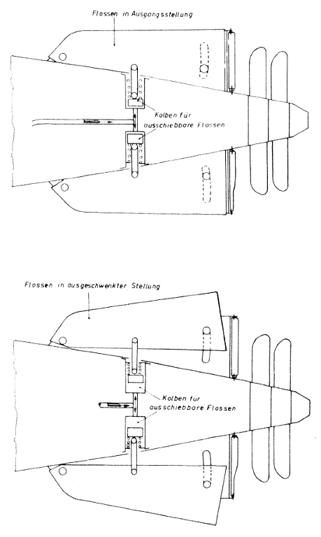
Drawing 16. The pistons extending the extensible vertical stabilizers
| Flossen in Ausgangsstellung | the stabilizers in the resting position |
| Flossen in ausgeschwenkter Stellung | the stabilizers in extended position |
| Kolben für ausschiebbare Flossen | the pistons extending the vertical stabilizers |
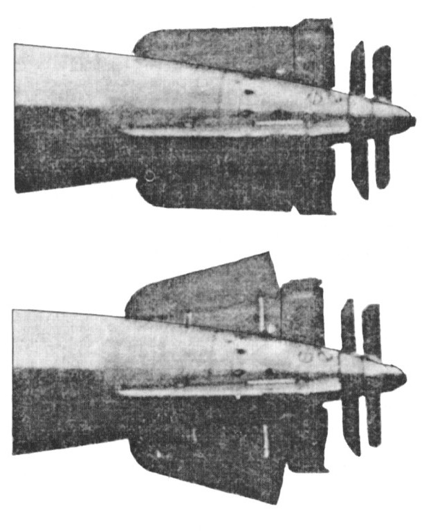
Photo 6. The extensible vertical stabilizers [4]
Photo 7. The extensible vertical stabilizers of the type G7e electric (Fat II) torpedo exhibited in MSI, Chicago (the pneumatic piston for extending the stabilizer is visible)

Photo 8. The top extensible vertical stabilizer of the type G7e electric (Fat II) torpedo exhibited in Muzeum Obrony Wybrzeża, Świnoujście (the upper part of the pneumatic piston for extending the vertical stabilizer is visible)
Photo 9. The extensible vertical stabilizers of the type G7e electric (Fat II) torpedo exhibited in Muzeum Obrony Wybrzeża, Świnoujście (the pneumatic piston extending the top vertical stabilizer is visible)
Although the problem with oscillatory heeling was solved, the concept of battery switching in order to increase the torpedo range was abandoned.
In the meantime, in the end of 1942, the new electric torpedo (designated as T III) entered the service. The new torpedo was a slightly modified type T II torpedo. Germans simply added a cable between battery compartment and head of torpedo, in order to provide power supply for the new type Pi 2 influence pistol.
For a very brief time, the Fat control gear was installed (despite a short range of maximum 5000 meters) in type T II and T III electric torpedoes.
In the beginning of 1943, the AFA company was ordered to develop the torpedo battery of greater capacity. In the Spring, AFA company delivered new type 17 T 210 battery, which consisted of two containers, 26-cell each. Each cell was built of 17 positive plates and 18 negative plates. The total capacity was equal to 130 Ah (when heated up to 30°C). The newly developed electric torpedo (designated as T IIIa) was powered by this type 17 T 210 battery and two additional cells (54 cell in total). Such arrangement provided energy for travelling (after heating up to 30° C) 7500 meters. The weight of type 17 T 210 battery was equal to 800 kg.
The extended running time (by over 2,5 minutes) required the larger compressed air storage (which was used to drive the gyro and steering engines). In the type T II and T III electric torpedoes, the compressed air was stored (under the pressure of 200 at) in three flasks of capacity 5 liters each, located in the aft part of the torpedo. The type T IIIa torpedo was fitted with additional spherical tank of capacity 15 liters, located in the forward part of the battery compartment.
The greater weight of the type 17 T 210 battery and additional compressed air tank increased the weight of the type T IIIa torpedo (comparing to the the weight of the type T II and T III torpedoes) by about 200 kg. Therefore, the negative buoyancy increased up to 500 kg. The increased negative buoyancy required to be compensated by increasing the hydrodynamic force generated at the torpedo hull. This in turn required greater attack angle. The greater attack angle was related with oscillatory heeling, which (apart from the leakage of the electrolyte) could result in premature activation of the type Pi 2 influence pistol. That's why type T IIIa torpedoes were fitted with (developed earlier, quite effective) extensible vertical stabilizers (ausschiebbare Flossen).
The Fat control gear for type T IIIa torpedoes was almost identical to the control gear for type T I wet-heater torpedoes. The main difference between them was a different set of the steering cams, and hence a different maneuvering patterns. Moreover, Fat control gear for the electric torpedoes was driven directly from the torpedo propeller shaft.
The available maneuvering patterns were lang links/rechts (the same as in case of wet-heater torpedoes, of the loop length of 1200 meters and 1800 meters). However, instead of kurz links/rechts pattern, the circling (to the left) pattern (of radius of 170 meters), so called Kreislauf was introduced. It was intended to use this circling pattern to self-defense against the destroyers attacking the U-Boat (as a temporary weapon, until the new type T V "Zaunkönig" homing torpedo entered the service).
However, the type T V homing torpedo entered the service in September 1943, so electric Fat torpedoes did not have opportunity to gain any successes in the anti-destroyer role.

Photo 10. The Fat pattern gear of the type G7e (T IIIa) electric (Fat II) torpedo, exhibited in Muzeum Obrony Wybrzeża, Świnoujście (comparing to the Fat pattern gear of the G7a wet-heater torpedo, one can note that bottom steering cams are identical and that pattern gear is driven directly from the propeller shaft)
Despite the different maneuvering patterns and shorter range (and hence shorter length of the preliminary straight run), it was decided not to develop different Fat setting gear. In the end of March 1943, the order was issued to use Fat setting gear dedicated for wet-heater torpedoes. The circling pattern was corresponding to the maneuvering pattern kurz (links or rechts).
Because electric torpedo was wakeless, the Fat torpedoes entered the service at first (in May 1943) in the areas, were wet-heater Fat torpedoes could not be used, i.e. on Mediterranean and Norther Waters (Norwegian Sea, Barents Sea and Kara Sea). Since June 1943, the Atlantic U-Boats were armed with electric Fat torpedoes, so they could use them to attack targets during the day, while submerged. Due to shorter range of the electric Fat torpedoes, it was found that other U-Boats in vicinity were not endangered and therefore there was no necessity to transmit the "Fat warning" before the attack.
In the initial period, the production rate of electric Fat torpedoes was only 100 per month.
Since the beginning of 1943, there were two, almost identical Fat control gears, designated for two types of torpedoes (wet-heater and electric torpedo), therefore, since the end of March 1943, the maneuvering versions of type T I wet-heater torpedoes (until then designated as Fat) were designated as Fat I, while maneuvering versions of the type T IIIa electric torpedoes were designated as Fat II.
The new terms: so called "Fat speed" (Germ. Fat-Geschwindigkeit) and so called "Fat course" (Germ. Fat-Kurs) are related with Fat torpedoes.
"Fat course" describes the general direction of the maneuvering torpedo, while "Fat speed" is the speed of advance along the "Fat course".

Drawing 17. The Fat speed and course (maneuvering pattern rechts kurz)
The "Fat course" is always perpendicular to the initial course of the torpedo, before it started to maneuver. To increase the chance for hitting the target, the "Fat course" should be parallel to the convoy general course.
The "Fat speed" depends on the length of the loop. For kurz pattern, this speed is equal to 8.5 knots, while for lang pattern, the speed is equal to 5.3 knots. The greatest chance for hitting the target in convoy is when the speed of convoy and "Fat speed" differs slightly. Therefore, the "Fat speed" for patterns kurz and lang were so adjusted to be close to the speed of the fast (of the speed 9-10 knots) and slow (of the speed 6-7 knots) convoys.
When Fat torpedoes entered the service, the only necessary adjustment required of the torpedo tubes was to drill the hole in the tube (for the Fat setting spindle) and to install Fat setting gear (Fat-Stellzeug).
It should be noted that torpedo tube with Fat setting gear installed could be also used to launch straight running, type T I wet-heater torpedoes as well as straight running type T II and T III electric torpedoes.
Likewise, the pattern running Fat I and Fat II torpedoes could be launched from the unmodified torpedo tubes (not fitted with Fat setting gear). Before loading to the unmodified tube, the maximum length of the preliminary straight run (Vorlauf) should be set at the torpedo. Then the launched torpedo acted as straight running torpedo.
The attack with Fat torpedoes was conducted in the similar way as in case of straight running torpedoes: the target data (speed and angle on the bow) were determined, then they were entered into the torpedo calculator. The calculator calculated the gyro angle, which was set at the torpedoes by means of the gyro angle setting spindle (W-Einstellspindel).
Then the distance to the target was estimated (or measured by radar), which (by means of the component for calculating maximum distance to target at the moment of the torpedo launch) was used to calculate the length of the preliminary straight run (Vorlauf).
Drawing 18. Distance to the target (Schußentfernung) and length of the preliminary straight run (Vorlauf)
Drawing 19. Reading out of the length of the preliminary straight run (Vorlauf) based on the distance to the target (Schußentfernung) from the component for calculating maximum distance to target at the moment of the torpedo launch
The calculated length of the preliminary straight run as well as selected maneuvering pattern (according to the speed and direction of convoy) was set by means of the Fat setting gear at the torpedo.
To make calculations of the length of the preliminary straight run easier, since 1943, the drum of the component for calculating maximum distance to target at the moment of the torpedo launch was fitted with new, detailed scale (instead of 7 lines corresponding to the maximum ranges of the German torpedoes, 24 lines were provided).
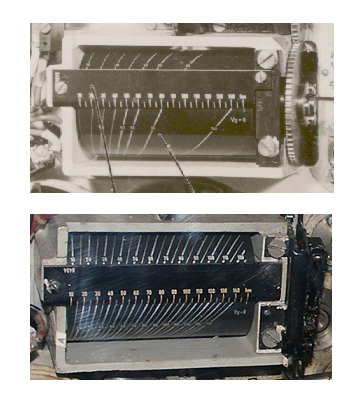
Photo 11. The component for calculating maximum distance to target at the moment of the torpedo launch: early version (before 1943) and late version (after 1943)
The U-Boats were armed with Fat torpedoes as soon as they were available particular torpedo depots, according the directives issued by BdU.
| 10.05.1943 | |||
| U-Boat type | Bow torpedo room | Aft torpedo room | Upper deck |
| Atlantic Ocean | |||
| VIIB, VIIC, VIID | 4 Fat I, 6 T III | 2 Fat II | |
| IXB, IXC | 4 Fat I, 6 T III | 2 Fat I, 2 Fat II | |
| IXD | 6 T III, 4 G7e | 4 G7e | 12 G7a |
| XB | 2 Fat II, 2 G7e | only if ordered | |
| Mediterranean and Northen Waters | |||
| VIIB, VIIC | 4 Fat II, 6 T III | 2 Fat II | |
| Black Sea | |||
| II | 5 T III | ||
| South Atlantic and Indian Ocean | |||
| IXC | 6 T III, 4 G7e | 2 Fat II, 2 G7e | |
| 01.04.1944 | |||
| U-Boat type | Bow torpedo room | Aft torpedo room | Upper deck |
| Atlantic Ocean | |||
| VIIC | 3 T V, 2 Fat I, 3 T III Fat II (or 5 T IIIa Fat II) |
2 T V | |
| VIID | 2 T V, 2 Fat I, 4 T III Fat II | 2 T V | |
| IXB, IXC | 3 T V, 3 Fat I, 4 T III Fat II (or 7 T IIIa Fat II) |
2 T V, 2 T III Fat II | |
| IXD | 2 T V, 8 T III Fat II (or 8 T IIIa Fat II) |
2 T V, 2 T III Fat II | 9 Fat I (or T I) |
| XB | 2 T V, 5 T III (or 5 Fat II) |
||
| Mediterranean | |||
| VIIC | 3 T V, 5 T IIIa Fat II | 2 T V | |
| Northen Waters | |||
| VIIC | 3 T V, 5 T III Fat II | 2 T V | |
| In case of U-Boats operating on Northen Waters, when Midnight Sun ended (i.e. since the end of August), three T I Fat I torpedoes would be loaded instead of three T III Fat II torpedoes. | |||
| Morze Czarne | |||
| II | 1 T V, 4 T III | ||
| 01.11.1944 | |||
| U-Boat type | Bow torpedo room | Aft torpedo room | Upper deck |
| Atlantic Ocean | |||
| VIIC | 3 T V, 5 T IIIa Fat II | 2 T V | |
| IXC | 4 T V, 5 T IIIa Fat II | 2 T V, 2 T IIIa Fat II | |
| IXD | 2 T V, 8 T IIIa Fat II | 2 T V, 2 T IIIa Fat II | 9 T I Fat I |
| XXIII | 2 T IIIa Fat II | ||
| Northen Waters | |||
| VIIC | 3 T V, 5 T IIIa Fat II | 2 T V | |
| Baltic Sea | |||
| VIIC | 3 T V, 5 T IIIa Fat II | 2 T V | |
Generally, initially the U-Boats were armed with Fat torpedoes according the following standard: Fat I torpedoes were loaded into forward torpedo room, while Fat II torpedoes were loaded into aft torpedo room. Fat II torpedoes (in circling mode) launched from aft tubes were intended to be anti-escort weapon. Only U-Boats operating on Mediterranean and Northern Waters received Fat II torpedoes only.
When type T V "Zaunkönig" homing torpedoes entered the service, they were designed as anti-escort weapon, loaded into aft tubes. The Fat II torpedoes (released from anti-escort function) began to be loaded into forward torpedo rooms.
Since November 1944, the U-Boats were armed with wake-less Fat II and T V electric torpedoes only (concerns only the U-Boats with tubes adjusted to Fat torpedoes).
The pattern running Fat were used since November 1942 until March 1945. At least 100 U-Boats were armed with them. At least 60 attack were conducted with maneuvering torpedoes. It is difficult to present more accurate statistics without thorough query of the U-Boats War Diaries (and associated firing reports, Germ. Schussmeldungen) of the particular boats (however such query does not guarantee success, because torpedo type was not always noted).
References:
[1] Federapparat für den Torpedo G7a Fat I, Beschreibung, Zeichnungen und Bedienungsvorschrift, 1942
[2] Report on the Interrogation of Survivors from U-664
[3] Manfred Schiffner, Karl-Heinz Dohmen, Ronald Friedrich, Torpedobewaffnung
[4] Eberhard Rössler, Die Torpedos der deutschen U-Boote