
")
Torpedo fire control system on German U-Boats
The final version of the torpedo fire control system (Germ. Torpedorichtungsweiseranlage or TRW in short) used on German U-Boats since 1942 was built around a torpedo data computer designated T.Vh.Re.3 by Siemens. This fire control system consisted of the following subsystems:
- aiming and target bearing transmitting subsystem
- Torpedo Data Computer (TDC), which solved the torpedo triangle and calculated the gyro angle and the torpedo spread angle
- gyro angle and torpedo spread angle transmitting subsystem from the torpedo computer to the torpedo rooms
- machine amplifier, which entered the calculated gyro angle into the gyro-gears of the torpedoes loaded into the tubes
- torpedo firing system
- power supply system
The torpedo fire control system described here is based on the type VIIC U-Boat, which was equipped with four bow torpedo tubes and one aft torpedo tube.
Many photographs were taken on board U 995, now a museum-ship in Laboe and it should be noted that most of the identification labels are not-original and often mistakenly located or mistakenly labelled. This results from double re-labelling (the first time when U 995 was commissioned into the Norwegian Navy and the second time when she was prepared for her role as a museum ship) and in many places one can find labels with Norwegian text because the original German labels were lost. In this document, I recreated the original labels based on the known hardware, which may not always match with the present labels on board U 995.
The particular elements of these subsystems are presented in drawing 1.
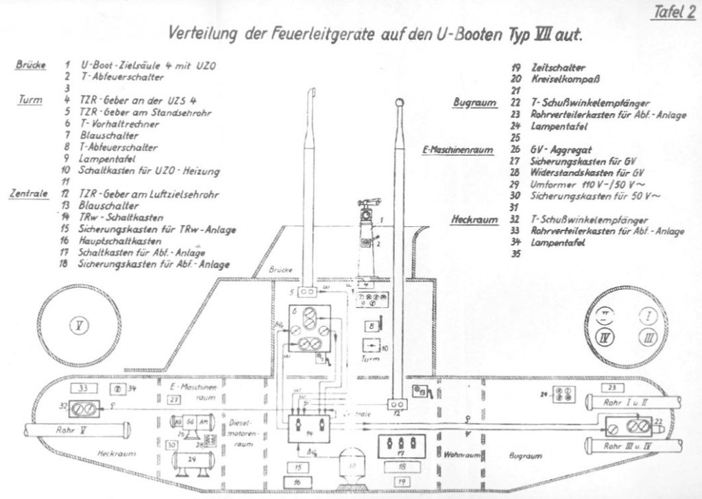
Drawing 1. Type VIIC U-Boat torpedo fire control system [1]
| Bridge: | 1 | The bridge aiming column UZO (U-Boot-Ziel-Optik) |
| 2 | Torpedo launch lever (T-Abfeuerschalter) | |
| 3 | ||
| Conning tower: | 4 | UZO target bearing transmitter |
| 5 | Attack periscope target bearing transmitter | |
| 6 | Torpedo data computer | |
| 7 | Target follow-up switch (Blauschalter) | |
| 8 | Torpedo launch lever (T-Abfeuerschalter) | |
| 9 | Torpedo tubes control lamps | |
| 10 | The UZO heating control box | |
| 11 | ||
| Control room: | 12 | Sky periscope target bearing transmitter |
| 13 | Target follow-up switch (Blauschalter) | |
| 14 | Aiming subsystem control box | |
| 15 | Aiming subsystem fuse box | |
| 16 | Main distribution box | |
| 17 | Torpedo firing subsystem control box | |
| 18 | Torpedo firing subsystem fuse box | |
| 19 | Timing control box | |
| 20 | Gyro-compass | |
| 21 | ||
| Forward torpedo room: | 22 | Gyro-angle receiver (T-Schußwinkelemfänger) |
| 23 | Torpedo firing subsystem distribution box | |
| 24 | Torpedo tubes control lamps | |
| 25 | ||
| E-motor room: | 26 | Rotary machine amplifier (GV-Aggregat) |
| 27 | Gyro-setting subsystem fuse box | |
| 28 | Gyro-setting subsystem control box | |
| 29 | Rotary converter powering the torpedo fire control system | |
| 30 | Aiming and TDC subsystems fuse box | |
| 31 | ||
| Aft torpedo room: | 32 | Gyro-angle receiver (T-Schußwinkelemfänger) |
| 33 | Torpedo firing subsystem distribution box | |
| 34 | Torpedo tubes control lamps | |
| 35 |
The aiming and target bearing transmitting subsystem automatically transmits up-to-date target bearing data from a selected aiming device (UZO or periscope) to the torpedo data computer.
The UZO and both periscopes were connected to target bearing transmitters (Torpedo-Ziel-Richtung Geber). They operated on the selsyn synchro link principle and transmitted the bearing directly to the torpedo data computer. Each target bearing transmitter consisted of two selsyn transmitters in order to achieve better accuracy. First, they transmitted the angle in the range of 0 – 360°, the second – in the range of 0 – 10°. The maximum transmitting speed was 12°/s.
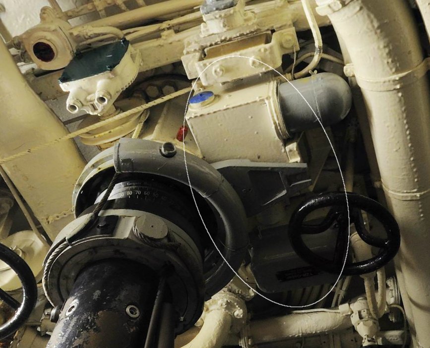
Photo 1. Target bearing transmitter coupled with the sky periscope in U 995’s control room [2]
The aiming device (UZO, attack periscope, or sky periscope) used during the attack was selected (connecting the proper target bearing transmitter with the computer) by means of one of the two rotary switches located at the aiming subsystem control box that was installed in the control room (under the chart table).
The main part of the fire control system was the electro-mechanical torpedo data computer (Torpedo-Vorhaltrechner) or TDC designed and manufactured by the Siemens Company. It was located in the conning tower on the starboard side between the helmsman’s station and the attack periscope. The computer solved the torpedo triangle and calculated the gyro angle and the torpedo spread angle. The current target bearing was entered automatically by means of selsyn links, however in an emergency, it could be set manually using the hand-wheel on the TDC. The other data: target speed, angle on the bow, torpedo speed and target length were set manually by means of the hand-wheels on the TDC.
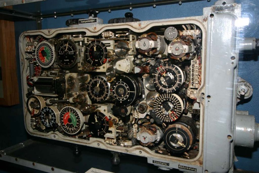
Photo 2. The torpedo data computer from U 995 at the exhibition
in the Marine-Ehrenmal in Laboe (with front cover removed)
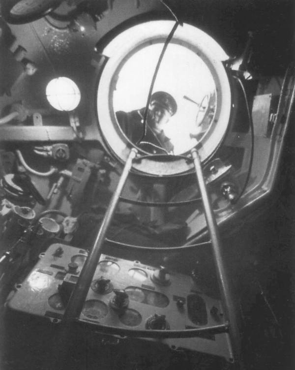
Photo 3. The torpedo data computer in a type VIIC U-Boat conning tower (most likely
U 995, visible in the hatch is – most likely - Kptlt. Walter Köhntopp) [3]
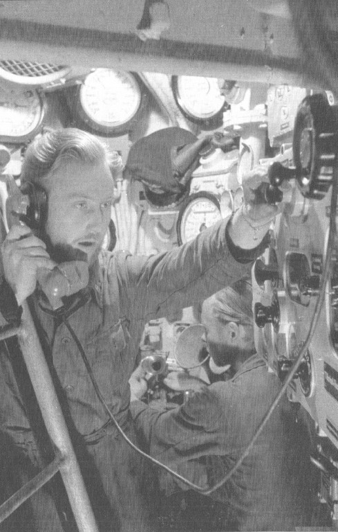
Photo 4. The operator of the torpedo data computer in a type VIIC U-Boat conning
tower [4]
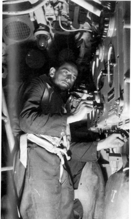
Photo 5. Oberbootsmann Heinz Webendörfer operates the torpedo data computer in U 564’s conning tower [5]
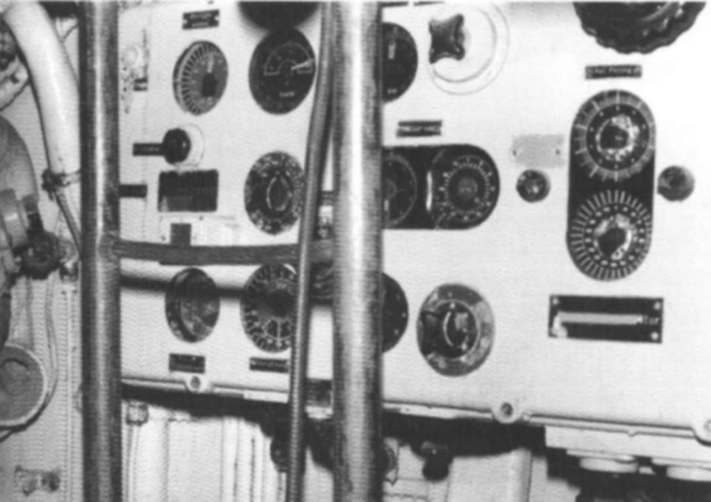
Photo 6. The torpedo data computer in U 995’s conning tower [3]
To correctly calculate the gyro angle, the torpedo data computer required the current U-Boat course which was transmitted by means of a selsyn link from the gyro-compass located in the control room.

Photo 7. Gyro-compass in U 995’s control room
The calculated gyro angle – together with the torpedo spread angle – was transmitted by means of selsyn links to the gyro angle receivers that were located in the forward and aft torpedo rooms.
The active gyro angle receiver was selected by means of the right hand rotary switch located on the aiming subsystem control box front panel, which was installed in the control room (under the chart table).
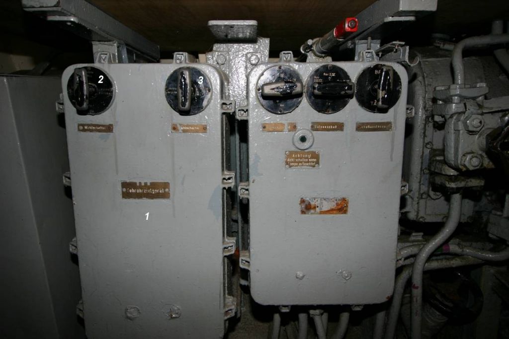
Photo 8. Aiming subsystem control box in U 995’s control room
| 1. | Aiming subsystem control box (Schaltkasten TRw-Anlage) |
| 2. | Target bearing transmitter select switch: UZO/sky periscope/off/attack periscope (Zielrichtung: UZO/Zentrale Sehrohr/Aus/Turm Sehrohr) |
| 3. | Gyro angle receiver select switch: off/forward/off/aft (Schußrichtung: Aus/Vordere Rohre/Aus/Achtere Rohre) |
The gyro angle receivers in the forward and aft torpedo rooms set - by means of dedicated shafts that penetrated into the torpedo tubes – the calculated gyro angle at the gyro-gears of the torpedoes. Because the selsyn receiver had not enough output power (torque) to train the gyro-setting gears directly, it was done by means of a servo-gear that was controlled by the machine amplifier (GV-Aggregat), which was located in the E-motor room.
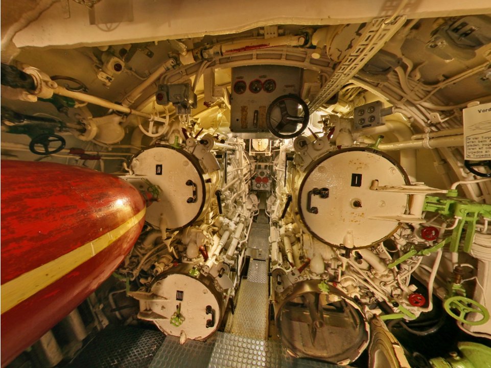
Photo 9. The gyro angle receiver in U 995’s forward torpedo room
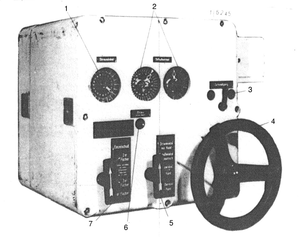
Photo 10. The gyro angle receiver for forward torpedo tubes [6]
| 1. | The torpedo spread dial in the range 0 – 20° |
| 2. | Double gyro angle dial – one dial in the range 0 -360°, second dial in the range 0 – 10° |
| 3. | High setting speed switch - Schnellgang |
| 4. | The hand-wheel for manually setting the gyro angle and torpedo spread angle |
| 5. | The angle setting mode select switch: Spread angle manually, gyro angle automatically/spread angle manually/gyro angle manually (Streuwinkel von Hand, Schusswinkel automatisch/ Streuwinkel von Hand/Schusswinkel von Hand) |
| 6. | Target follow-up control lamp - Blau (nicht folgen) |
| 7. | The torpedo salvo size select switch: Single shot/2-torpedo salvo/3-torpedo salvo/4-torpedo salvo (Salvo size select switch can be changed-over only when spread angle is set to “0”) (Einzelschuss/2er Fächer/3er Fächer/4er Fächer (Fächer einstellen nur wenn Streuwinkel Folgezeiger auf „0” steht)) |
The gyro angle receiver for the forward torpedo tubes consisted of:
- DC motor controlled by the machine amplifier
- The selsyn receiver for the torpedo spread angle, coupled with a double dial in the range 0 – 20°. This dial has a window pointer rotating along the dial edge which shows the angle calculated by computer and a pointer rotating on the center axis which shows the currently set torpedo spread
- Two selsyn receivers for the gyro angle; to increase accuracy the first receiver's input range was 0 – 360°, the second receiver's input range was 0 – 10°. The receivers were coupled with two dials. The pointers rotating along the dial edges showed the angle calculated by the computer, while the pointers rotating on the center axis showed the currently set gyro angle
- target follow-up control lamp - Blau (nicht folgen)
- three-way angle setting mode select switch: Spread angle manually, gyro angle automatically/spread angle manually/gyro angle manually (Streuwinkel von Hand, Schusswinkel automatisch/Streuwinkel von Hand/Schusswinkel von Hand)
- four-way torpedo salvo size select switch: Single shot/2-torpedoes salvo/3-torpedoes salvo/4-torpedoes salvo (Salvo size select switch can be changed-over only when spread angle is set to “0”) (Einzelschuss/2er Fächer/3er Fächer/4er Fächer (Fächer einstellen nur wenn Streuwinkel Folgezeiger auf „0” steht))
- the hand-wheel for manually setting the gyro angle and torpedo spread angle
- high setting speed switch – Schnellgang – together with two control lamps – red on the left side and green on the right side
- four differential gears (one for each torpedo tube), which added the gyro angle (set by DC motor or entered manually) with the torpedo spread angle (entered manually)
- two gears, which – depending on the torpedo salvo size selection – provided the following ratios: 1:0,5, 1:1, 1:1,5 and 1:-0,5, 1:-1, 1:-1,5.
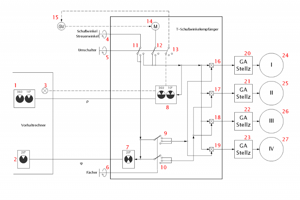
Drawing 2. The functional diagram of the gyro angle receiver for forward torpedo tubes
| 1. | Gyro angle transmitter at the TDC |
| 2. | Torpedo spread angle transmitter at the TDC |
| 3. | Control lamp signaling that gyro gears at torpedoes were set to the angle transmitted from the TDC (Deckungslampe) |
| 4. | The hand-wheel for manually setting the gyro angle and torpedo spread angle |
| 5. | Three -way angle setting mode select switch: Streuwinkel von Hand, Schusswinkel automatisch/Streuwinkel von Hand/Schusswinkel von Hand |
| 6. | Four-way torpedo salvo size select switch: Einzelschuss/2er Fächer/3er Fächer/4er Fächer |
| 7. | The torpedo spread angle receiver |
| 8. | The gyro angle receiver |
| 9, 10. | The gears with switchable ratio |
| 11. | The part of the angle setting mode select switch responsible for setting the torpedo spread angle |
| 12. | The part of the angle setting mode select switch responsible for setting the gyro angle |
| 13. | The part of the angle setting mode select switch responsible breaking the feedback loop (disabling the DC motor) while setting the gyro angle manually |
| 14. | DC motor for driving gyro setting gears |
| 15. | Machine amplifier |
| 16, 17, 18, 19. | Differential gears |
| 20, 21, 22, 23. | Torpedo tube gyro setting gears |
| 24, 25, 26, 27. | Torpedo tubes |
The gyro angle receiver could work in two modes – automatic and manual.
In automatic mode, the angle setting mode select switch was set to the position Streuwinkel von Hand, Schusswinkel automatisch. In this mode, the gyro angle dials created the differential signal between the gyro angle value received from the TDC and the gyro angle value actually set at the torpedoes. This differential signal was presented on the dials by the relative positions of the inner and outer pointers. The differential signal was amplified by the machine amplifier (GV Aggregat) which controlled the DC motor. The DC motor drives the shafts connected with the torpedo tube gyro setting gears. In that way, the whole subsystem sought to minimize the differential signal, respectively turning the torpedo's gyro setting gears according to the value received from the TDC. So the setting DC motor – machine amplifier looked like a servo-motor controlled in a feedback loop.
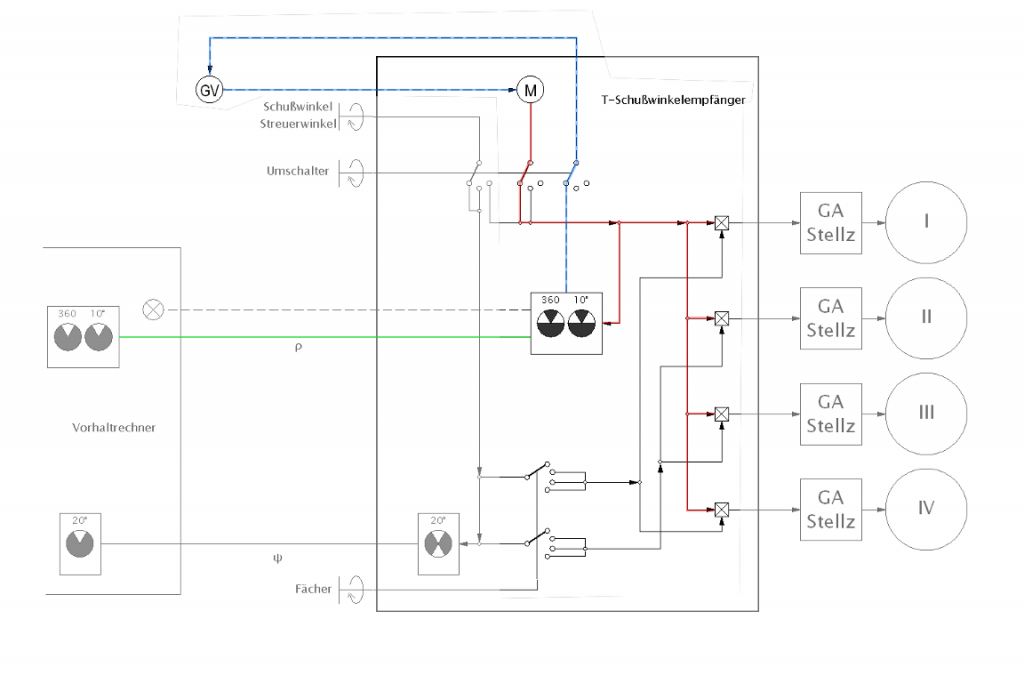
Drawing 3. The operation of the gyro angle receiver in the automatic mode
(single shot – all torpedo tubes received the same gyro angle value)
green – gyro angle received from the TDC
blue – differential signal amplified by the machine amplifier,
which controlled the DC motor
red – gyro angle value entered into the torpedoes
The DC motor shaft was coupled with the shafts of each torpedo tube by four differential gears. Thus the gyro angle calculated by the TDC could be modified by the torpedo spread angle value for each torpedo tube. The value of the torpedo spread angle was entered manually by the hand-wheel. The gyro angle receiver operator trained the hand-wheel until the set torpedo spread angle was the same as the value calculated by the TDC. The torpedo spread angle was passed to the differential gears through two gears with switchable ratios. These gears implemented the multiplication by a constant. Both gears had three ratios: 1:0.5, 1:1 and 1:1.5, but each gear rotated in an opposite direction (that is the output values were the same, but their signs were opposite).
The drawing below represents the operation of the gyro angle receiver in the automatic mode when a three-torpedo salvo was selected. The DC motor rotates the differential gears to the value ρ (red). By means of the hand-wheel, the torpedo spread angle ψ (green) is entered, which is passed through one of the two gears (in the three-torpedo salvo mode, its ratio is 1:1) into two differential gears, where it's added to the gyro angle ρ. In the other gear (in the three-torpedo salvo mode, its ratio is 1:-1) the sign of the value ψ is reversed (blue) and passed into the other two differential gears, where it's subtracted from the gyro angle ρ.

Drawing 4. The connections between the DC motor and torpedo tube gyro angle setting gears
in the automatic mode, when a three-torpedo salvo is selected
The torpedo salvo size select switch was used to change the salvo size. It was possible to select:
- single shots (Einzelschuss) – the gyro angle sent to each torpedo tube was the same;
- 2-torpedo salvo (2er Fächer) - the gyro angle ρ for two torpedo tubes was modified in the following way:
- torpedo tubes I and II: ρ + 0,5 ψ
- torpedo tubes III and IV: ρ - 0,5 ψ
- tubes I and III
- tubes I and IV
- tubes II and III
- tubes II and IV
- 3-torpedo salvo (3er Fächer) - the gyro angle ρ for three torpedo tubes was modified in the following way:
- torpedo tube I: ρ + ψ
- torpedo tubes II and III: ρ
- torpedo tube IV: ρ – ψ
- tubes I, II and IV
- tubes I, III and IV
- 4-torpedo salvo (4er Fächer) - the gyro angle ρ for four torpedo tubes was modified in the following way:
- torpedo tube I: ρ + 1,5 ψ
- torpedo tube II: ρ - 0,5 ψ
- torpedo tube III: ρ + 0,5 ψ
- torpedo tube IV: ρ - 1,5 ψ
The final angle between two torpedoes in a salvo depended on the salvo size and for a 2-torpedo salvo was equal to ψ, for a 3-torpedo salvo was equal 2ψ, and for a 4-torpedo salvo - 3ψ. The angle between the courses of particular torpedoes in a salvo also depended on the number of torpedoes and was equal to: 0.5ψ for a 2-torpedo salvo and ψ for a 3 and 4-torpedo salvo.
The torpedo salvo size select switch should only be changed when the spread angle was set to “0”. Otherwise, the gyro angles set in the gyro gears of the particular torpedoes would be incorrect. For example: initially when a 4-torpedo salvo was selected, the gyro angle was set to 20° and spread angle to 2°. The gyro gears of the particular torpedoes were set as follows: 23°, 19°, 21°, and 17°. If the salvo size select switch was changed to a single shot (that is gyro gears of all torpedoes intended to be set to 20°), there would be a situation where the current set values were different than values set on the gyro angle receiver. If the gyro angle was set to 30° and the error was not spotted, then the gyro angles set on the torpedo gyro gears would be as follows: 33°, 29°, 31°, and 27° instead of 30°. The proper change-over to a single shot should be preceded by zeroing the spread angle (then the gyro gears of all the torpedoes would be set to 30°).
The servo was turned on when the difference between the actually set gyro angle and gyro angle calculated by the TDC was as small as 0.5°. When the gyro angle actually set was equal to the gyro angle calculated by the TDC, the control lamp (Deckungslampe). lit up. When the gyro angle received from the TDC was changing rapidly (with a speed greater than the so-called follow-up speed – (Nachsteuergeschwindigkeit) of the DC motor (which is 2°/s), the current gyro angle is not in alignment with the value calculated by the TDC. In such a case the control lamp (Deckunglampe) was turned off, so the TDC operator knew that the gyro-angle gears of the torpedoes are not set to the desired value. Simultaneously the speed of the DC motor increased to 2.5 – 3°/s.
When the gyro angle calculated by the TDC changed by a large value (i.e. after a target change, the gyro angle could change from 290° to 75°), the gyro angle receiver operator can receive the order to speed up the process of aligning the torpedoes’ gyro-angle gears with the value calculated by the TDC. After receiving such an order, the operator set the high setting speed switch – Schnellgang – respectively to the right or left. Then the DC motor ran on the respective side with a speed of 4.5 – 5°/s. The direction to set the high setting speed switch was indicated by two control lamps located on both sides of the switch (left side – red, right side – green). When the actually set gyro angle was close to the value calculated by the TDC, the switch was set in the middle position and the servo automatically completed alignment at a speed of 2°/s.
The gyro angle receiver manual mode was used when the DC motor or machine amplifier was damaged or when the link transmitting the gyro angle (and torpedo spread angle) from the TDC to receiver was broken. In such a case, the setting mode select switch was switched to the position Schusswinkel von Hand. The hand-wheel is then coupled with the DC motor shaft. While looking at the dial pointers, the desired gyro angle was set manually by means of the hand-wheel. When only the DC motor and machine amplifier were damaged and the transmission link between the TDC and receiver was operational, the gyro angle calculated by the TDC was visible on the dials. When the transmission link was broken the desired value was passed verbally. When the desired value of the gyro angle was entered, the setting mode select switch was set to position Streuwinkel von Hand (torpedo spread angle manually) and the torpedo spread angle was entered similarly.
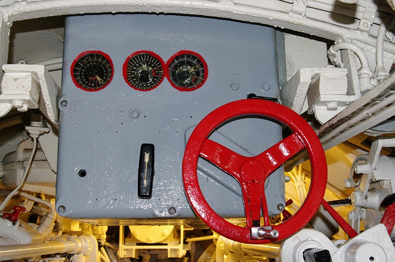
Photo 11. The gyro angle receiver in U 995’s forward torpedo room
The outputs of the differential gears were connected with the gyro-angle setting gears of the torpedo tubes by means of the shafts.

Photo 12. Back view of the gyro angle receiver in U 995’s forward torpedo room
| 1. | Gyro angle receiver |
| 2. | The U-joints of the differential gear outputs, which where coupled with the gyro-angle setting gears of the torpedo tubes by means of the shafts (upper pair for starboard tubes, lower pair for port tubes) |
| 3. | Uncoupled shaft connecting the differential gear with the gyro-angle setting gear of the lower, starboard torpedo tube (III) |
| 4. | DC motor controlled by the machine amplifier |
| 5. | The compressed-air motor for driving the capstan |
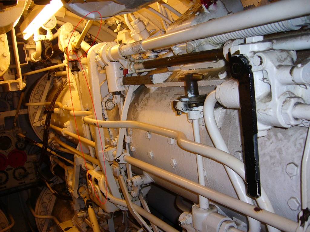
Photo 13. The shaft coupling the differential gear output with the gyro-angle
setting gear of the lower, starboard torpedo tube (III)

Photo 14. Uncoupled shaft connecting the differential gear output with the gyro-angle
setting gear of the lower, port torpedo tube (IV)
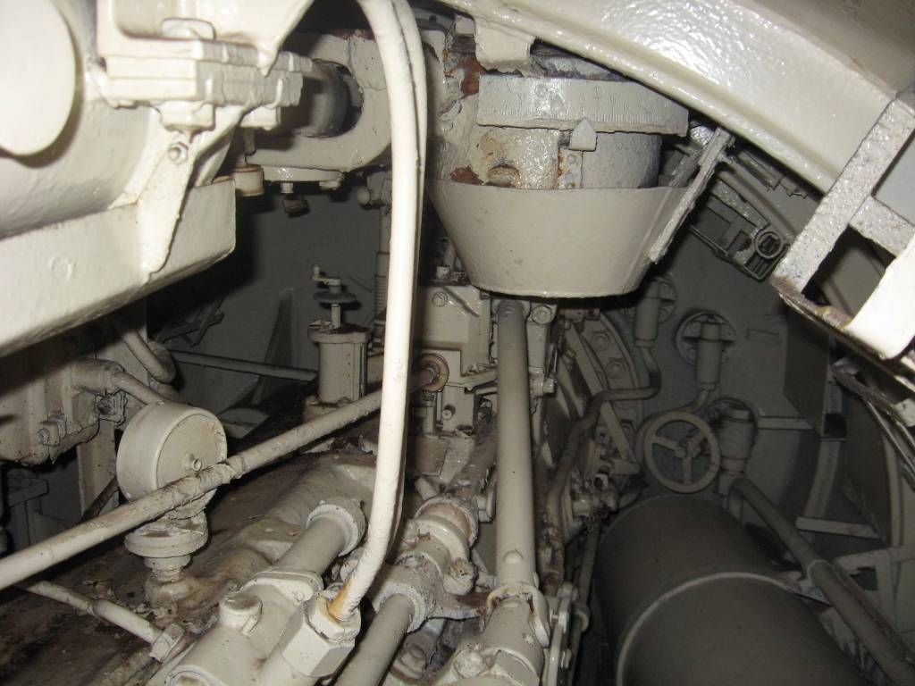
Photo 15. The shaft coupling the gyro angle receiver with the gyro-angle setting gear of the aft torpedo tube (V) in U 995’s aft torpedo room, at the left the hand-wheel for setting torpedo running depth is visible
The main part of the gyro-angle setting gear at the torpedo tube was the shaft that was inserted into the torpedo tube through the tube wall. This shaft was inserted into a dedicated slot in the torpedo. While turning, this shaft changed the torpedo gyro setting. At the moment of the torpedo launch, the shaft was automatically retracted by means of the firing rod, thus the torpedo was not blocked while leaving the tube. If this shaft failed to retract, the result could be a “tube runner” because the torpedo couldn’t leave the tube.
To simplify the system, the servo-motor driving the gyro-angle gears was installed only in the forward torpedo room. The receiver in the aft torpedo room consisted only of the selsyn receiver coupled with the dial and the hand-wheel driving the gyro-angle gear. The tube operator observed the dial and manually set the desired gyro angle at the gyro-angle gear of the torpedo loaded into the aft torpedo tube.
For the obvious reason (only one tube), the torpedo spread angle was not transmitted to the receiver installed in the aft torpedo room of the type VIIC U-Boats.
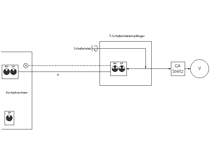
Drawing 5. A functional diagram of the gyro angle receiver for the single aft torpedo tube

Photo 16. Gyro angle receiver in U 995’s aft torpedo room
| 1. | The gyro angle double dial – one dial in the range 0 - 360°, the other in the range 0 – 10° |
| 2. | The hand-wheel for manually setting the gyro angle |
The torpedo firing subsystem was responsible for remotely launching torpedoes from the bridge or conning tower. Torpedo launching was done after triggering the firing lever (Abfeuerschalter). One such lever was located on the bridge, on the side of the UZO pedestal, while the other was in the conning tower near the torpedo data computer (left, below).
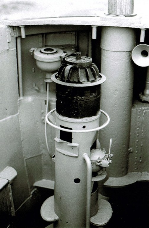
Photo 17. Firing lever on U 995’s bridge
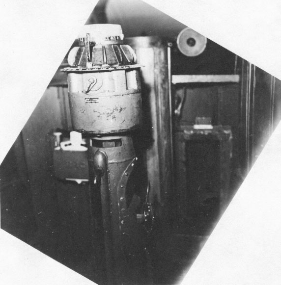
Photo 18. Firing lever on U 570’s bridge [7]
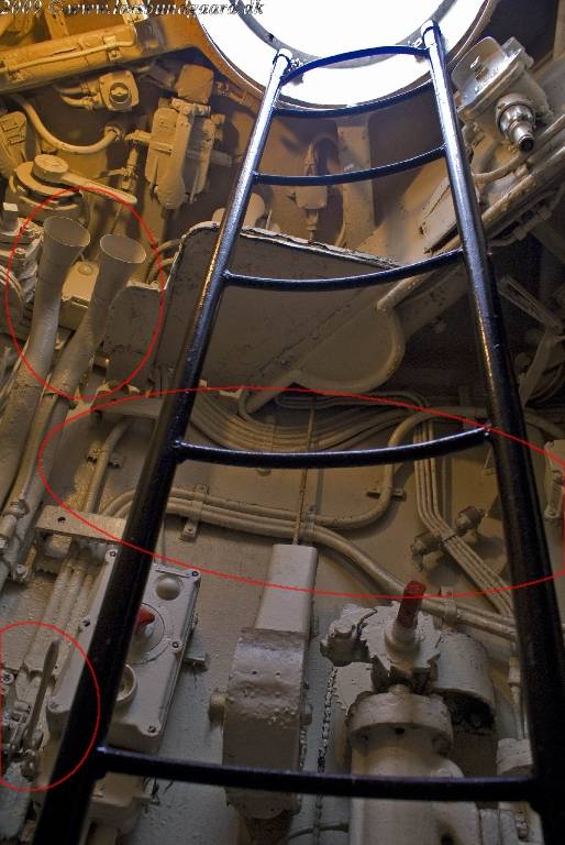
Photo 19. Firing lever in U 995’s conning tower. The mountings, where the torpedo data computer was installed are also visible as are two voice pipes used to communicate with the forward and aft torpedo rooms [8]
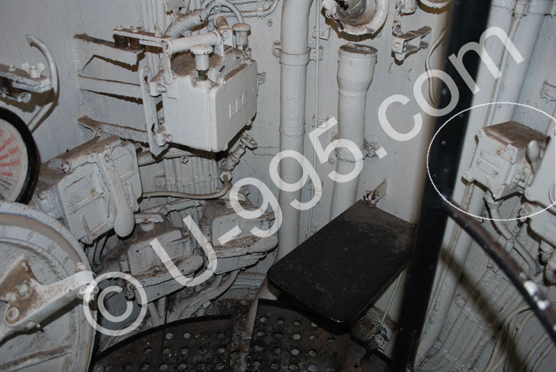
Photo 20. Firing lever in U 995’s conning tower [9]
The active firing lever selection was done by means of the right hand rotary switch located on the torpedo firing subsystem control box front panel that was installed in the control room (under the chart table).
The rotary switch to the left is responsible for choosing which torpedo tube to launch with a single shot or to select the salvo mode (torpedo tube I, II, III, IV, V or salvo shot). The middle rotary switch was used for a salvo mode shot and to choose the proper combination of tubes to initiate a launch. There were eight different combinations, as follows:
tubes I, II, III, IV
tubes I, II, IV
tubes I, III, IV
tubes II, III, IV
tubes II, III
tubes I, III
tubes II, IV
tubes I, IV
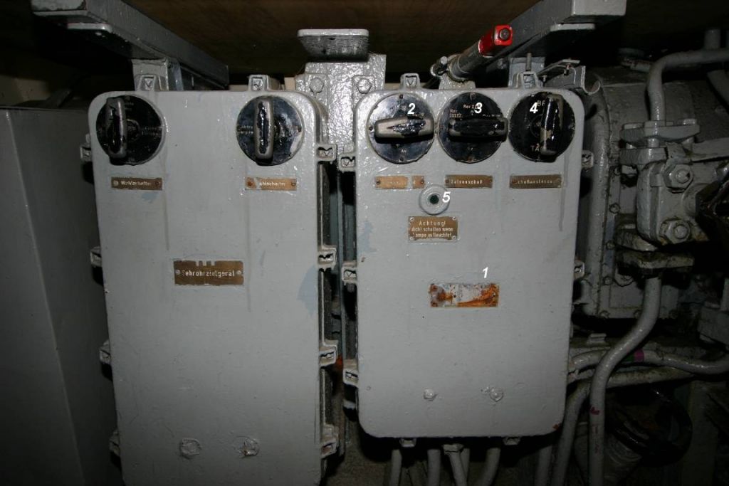
Photo 21. The torpedo firing subsystem control box in U 995’s control room
| 1. | The torpedo firing subsystem control box (Schaltkasten T. Abf. Anl.: Torpedo Abfeuer Anlage) |
| 2. | Switch for selecting the torpedo tube(s) to fire (Einzelnschuß: I/II/III/IV/V/Fächer) |
| 3. | Switch for selecting salvo configuration (Fächer: I II III IV/I II IV/I III IV/II III IV/II III/I III/II IV/I IV) |
| 4. | Switch for selecting the active firing lever: bridge/off/conning tower/off (T. Abf. Schalter: Brücke/Aus/Turm/Aus) |
| 5. | The control lamp, which lit-up, when the salvo shot was initiated – when lit-up, none of the switches on the firing subsystem control box should be changed (Achtung! Nicht schalten wenn Lampe aufleuchtet) |
In the case of launching a salvo, at the moment of triggering the firing lever, the first torpedo was launched. Simultaneously the timing control box (Zeitschalter) was turned on, which launched the other torpedoes automatically at a 2-3 second interval (later changed to a slightly larger interval to keep the torpedo wakes from influencing the course of the other torpedoes). Simultaneously, the control lamp at the firing subsystem switch box lit-up – when it was lit-up (that is the whole salvo was not launched yet), none of the switches should be changed. The timing control box generated the required delay between the launching of subsequent torpedoes by means of a simple spring-cam mechanism, triggered by an electro-magnet.
The torpedoes left the tubes in the following order: I, III, II, IV.
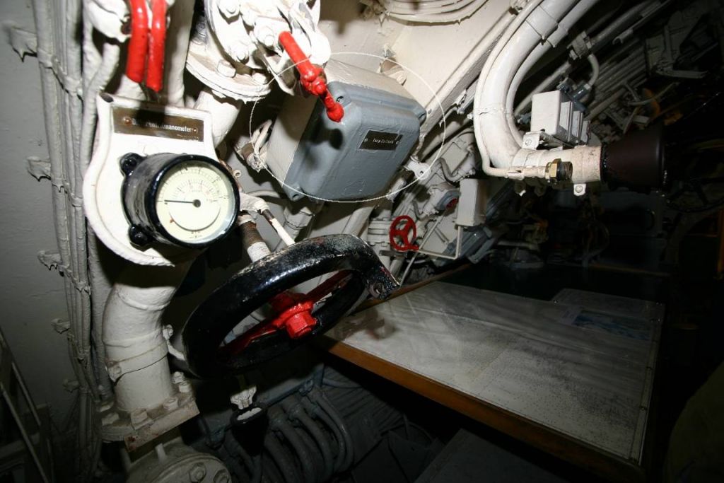
Photo 22. Timing control box in U 995’s control room
After triggering the firing lever, an electromagnet released the firing rod at the torpedo tube.
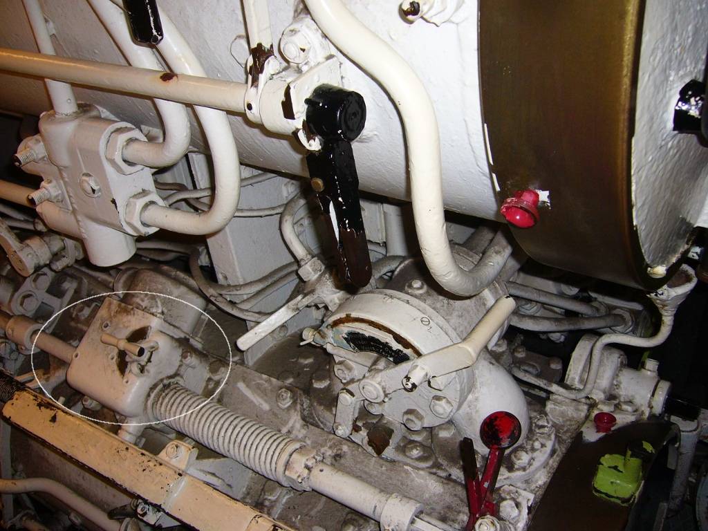
Photo 23. The firing electromagnet of forward torpedo tube III on U 995
The torpedo firing subsystem contained control lamps which showed the state of the torpedo tubes. One box with control lamps (five lamps – one lamp for each tube) was located in the conning tower, the second (with four lamps) in the forward torpedo room and the third (with a single lamp) – in the aft torpedo room. After selecting the desired tubes to fire (by means of the rotary switch on the torpedo firing subsystem control box), the respective lamps lighted up (each lamp was powered with low voltage so the light was dim). In such a state, it signalled the torpedo officer that the installation is operational and the tubes were selected properly. When the torpedo officer triggered the firing lever, the electromagnet released the firing rod. Simultaneously the control lamp of the corresponding tube became very bright. The tube operator in the torpedo room observed the lamps, and when he saw this he knew the torpedoes were being launched remotely. If the torpedo had not launched, then they launched the torpedoes manually. Thus the torpedo would always be fired – even if remote launching failed.
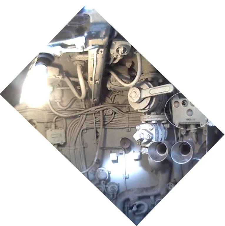
Photo 24. The control lamps in U 995’s conning tower
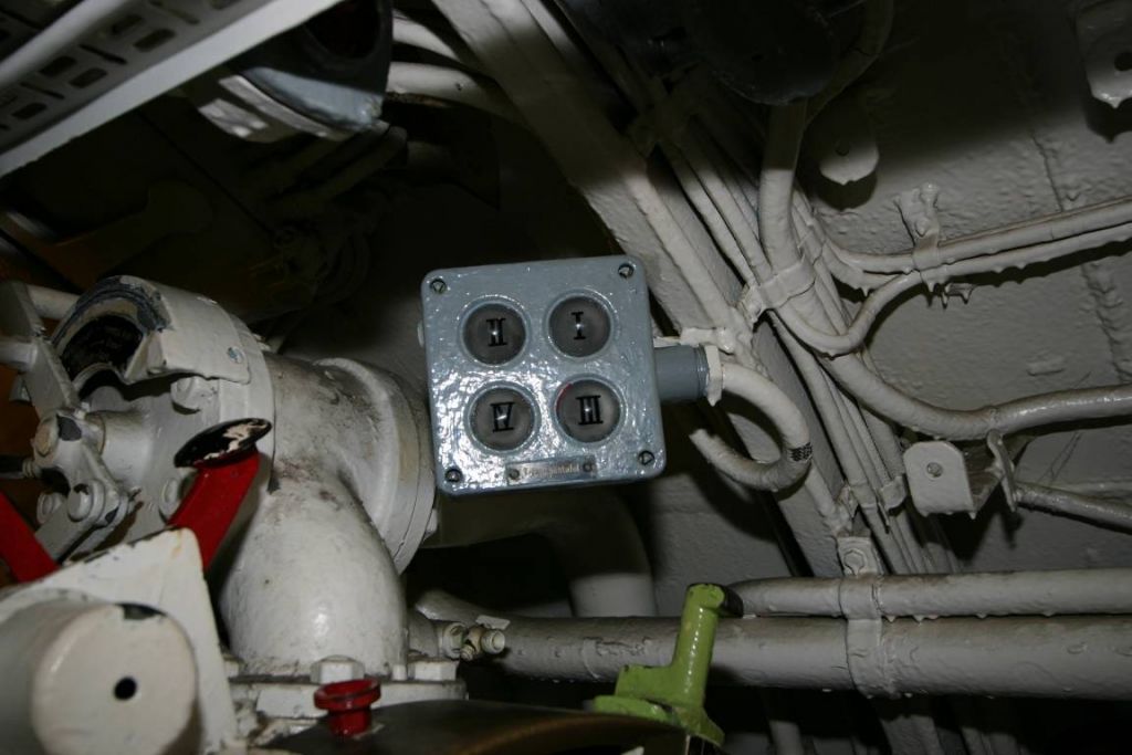
Photo 25. The control lamps in U 995’s forward torpedo room

Photo 26. Single control lamp in U 995’s aft torpedo room
Another essential part of the aiming subsystem was the target follow-up switch (Blauschalter) located in the conning tower and control room. When it was turned off, the target bearings from the target bearing transmitter were transmitted to the TDC with the up-to-date calculated gyro angle. When the follow-up switch was on, the target bearing was not transmitted to the TDC and the periscope could be turned (i.e. to search the whole horizon) without fear that the gyro-angle gears in the torpedoes would be set to an incorrect value.
Each switch was integrated with the control lamp. The similar lamp was located at the front panel of the TDC. The lamp lit up when the switch was turned on (the target bearing was not transmitted to the TDC).
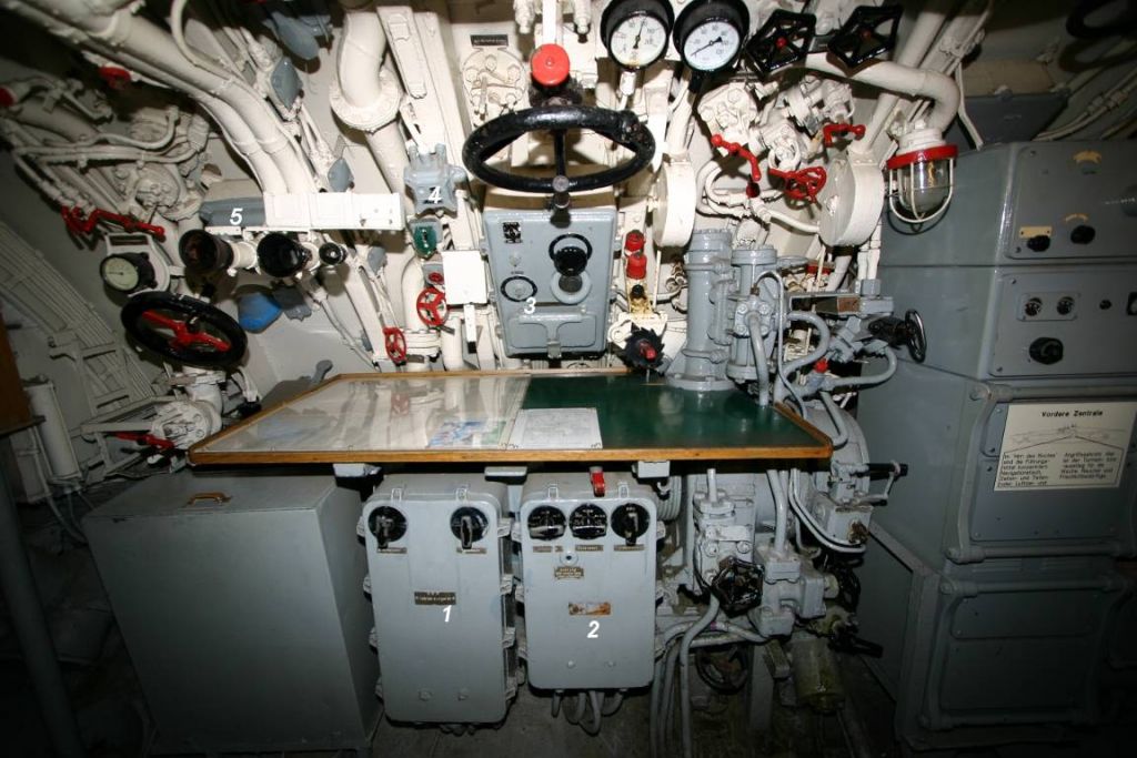
Photo 27. The components of the torpedo fire control system in U 995’s
control room – visible are the control boxes of the aiming and torpedo
firing subsystems, the main distribution box, target follow-up
switch and timing control box
| 1. | The aiming subsystem control box |
| 2. | The firing subsystem control box |
| 3. | The main distribution box |
| 4. | Target follow-up switch |
| 5. | Timing control box |
The described torpedo fire control system required two power supplies – the DC part (110 V) was powered from the ordering and reporting installation (B u M Gr 1c) through auxiliary switchboard 2 (in the control room), while the AC part (55 V, mainly selsyns) – by a rotary converter (TRw Umformer) located in the E-motor room which was in turn powered from auxiliary switchboard 1 (installed in the E-motor room).
The main distribution box which held fuses and the controllers of the rotary converter and machine amplifier was located in the control room, over the chart table.
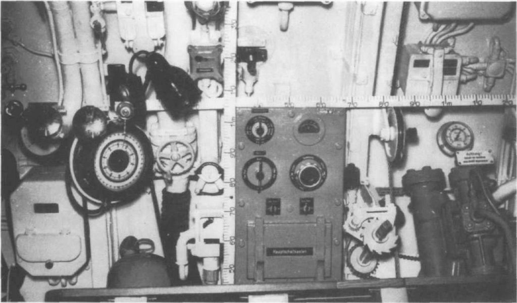
Photo 28. Main distribution box in U 98’s control room, the target follow-up switch is also visible [10]
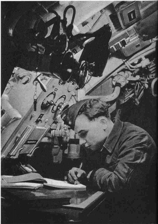
Photo 29. Main distribution box in U 96’s control room [11]

Photo 30. Main distribution box in Laubie’s control room (ex-U 766)
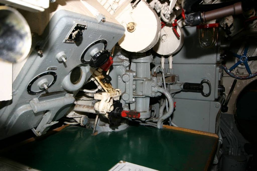
Photo 31. Main distribution box in U 995’s control room
The other types of German U-Boats equipped with a different number of torpedo tubes (type II – 3 forward torpedo tubes, type IX – 4 forward torpedo tubes and 2 aft torpedo tubes, type XB – 2 aft torpedo tubes) were fitted with a torpedo fire control system built from the same parts. They differed mainly in the type of aft gyro angle receivers, which were adjusted to the number of the aft torpedo tubes (type VII – one tube, types IX and XB – two tubes), control lamp boxes (due to the different number of torpedo tubes), and location of the control boxes (in the conning towers of the larger boats and in the control room of type VII boats) and the TDC (in the control room of type II boats and in the conning towers of other types).
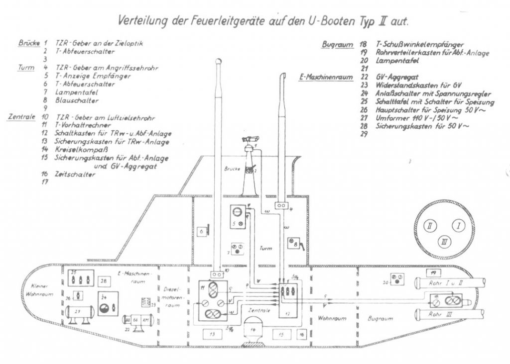
Drawing 6. Torpedo fire control system on type II U-Boats [1]
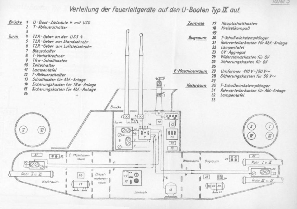
Drawing 7. Torpedo fire control system on type IX U-Boats [1]
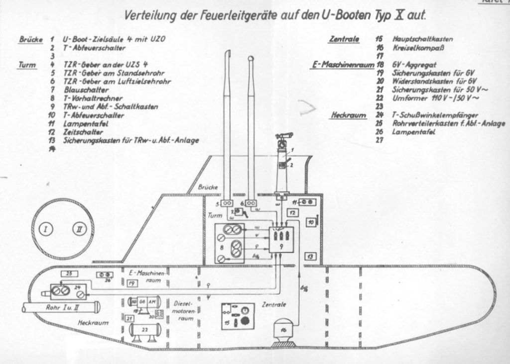
Drawing 8. Torpedo fire control system on type XB U-Boats [1]
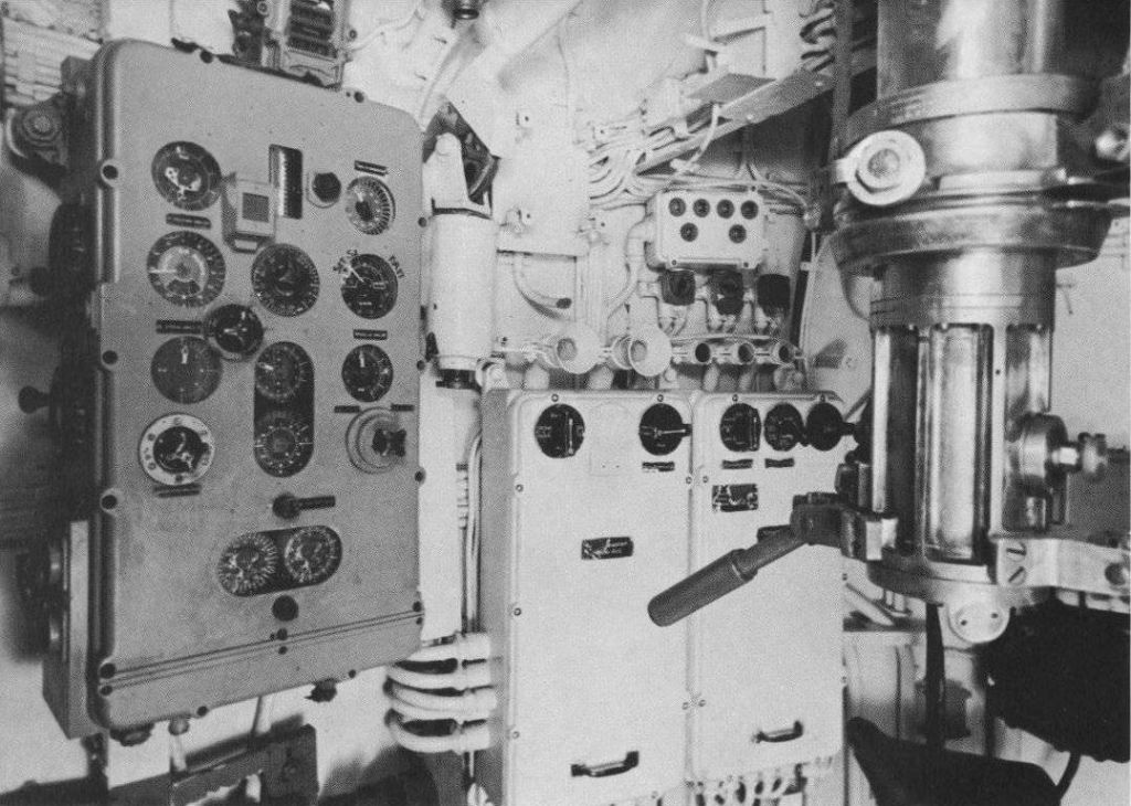
Photo 32. The elements of the torpedo fire control system in U 505’s conning tower,
visible are the TDC, control boxes and control lamps [12]

Photo 33. The gyro angle receiver for aft torpedo tubes of the type IX and XB U-Boats [6]
| 1. | The gyro angle double dial – one dial in the range 0 - 360°,the other in the range 0 – 10° |
| 2. | The torpedo spread angle dial in the range 0 – 20° |
| 3. | The hand-wheel for manually setting the torpedo spread angle |
| 4. | The hand-wheel for manually setting the gyro angle |

Photo 34. The gyro angle receiver (above the starboard torpedo tube) in U 505’s aft torpedo room [13]

Photo 35. The gyro angle receiver (above the starboard torpedo tube) in U 234’s aft torpedo room
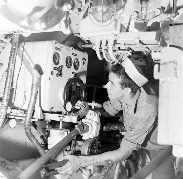
Photo 36. The gyro angle receiver (above the starboard torpedo tube) in U 234’s aft torpedo room
A modification of the described torpedo fire control system was installed (intended to be temporary because an entirely new system was under development, but due to the war ending it was never finished) on the type XXI U-Boats. These boats were fitted with six bow torpedo tubes so a set of two receivers was used to enter the gyro angle – one standard receiver (with DC motor) driving the gyro angle gears of the four torpedoes (from I to IV) and one standard receiver for aft torpedo tubes of the type IX and XB U-Boats (with manual setting of the gyro angle and torpedo spread angle) for driving the gyro angle gears of the remaining two tubes (from V to VI). The torpedo data computer was installed in the conning tower.
Demonstration showing the operation of the described torpedo control system is available here.
References:
[1] Torpedo-Schießvorschr. f. U-Boote, 1943
[2] Kubische Panoramen - Laboe - U-Boot U995 - Vordere Zentrale
[3] U 995, Wetzel Eckard
[4] U-Boot VII C, Jacques Alaluquetas
[5] U-Boat War Patrol: The Hidden Photographic Diary of U-564, Lawrence Paterson
[6] Torpedo Fire Control Installation in U-Boats Type XXI, 1944
[7] Photographs of U-570 taken during inspection by U.S. Navy Officers (Enclosure C to ONI report)
[8] Courtesy of Lars Bundgaard (larsbundgaard.dk)
[9] U-995.com
[10] Vom Original zum Modell, Uboottyp VIIC, Köhl, Fritz
[11] Jäger im Weltmeer, Lothar-Günther Buchheim
[12] The story of the U-505, Museum of science and industry, Chicago
[13] Museum of Science and Industry, Chicago, U 505 Submarine