
")
Torpedo launching procedures on U-Boats
In German armed forces (Wehrmacht) there were a whole range of the regulations (Dienstvorschriften). Depending on the forces (army, air force, navy), these regulations were divided into so called H.Dv. (Heer Dienstvorschriften), L.Dv. (Luftwaffe Dienstvorschriften) and M.Dv. (Marine Dienstvorschriften). They contained the field regulations, descriptions of the weapon systems, operating manuals of the communication systems and so on. The set of these regulations can be viewed on this website: http://www.superborg.de/
The text below is the translation of the German torpedo launching procedures - M.Dv.416/3 Torpedo-Schießvorschrift für U-Boote. Here are available the photos of the original document, here is the German version converted into html format.
Appendix
Table 1
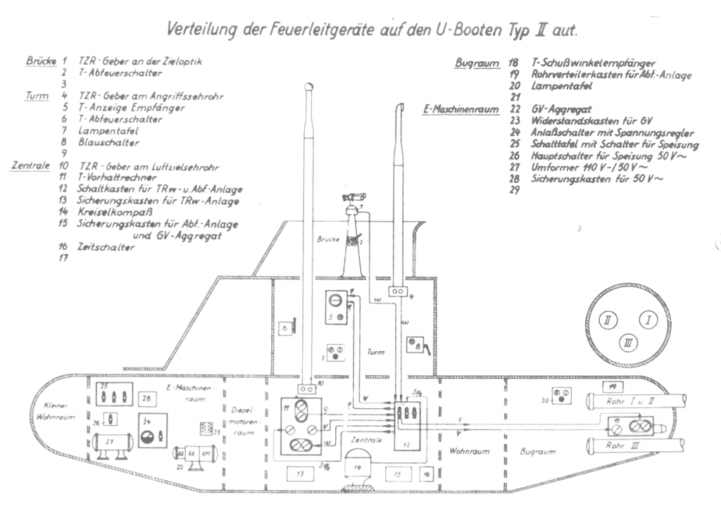
| Bridge: | 1 | The bridge aiming column UZO (U-Boot-Ziel-Optik) with target bearing transmitter |
| 2 | Torpedo launch lever (T-Abfeuerschalter) | |
| 3 | ||
| Conning tower: | 4 | Attack periscope target bearing transmitter |
| 5 | The gyro angle and salvo spread angle repeater | |
| 6 | Torpedo launch lever (T-Abfeuerschalter) | |
| 7 | Torpedo tubes control lamps | |
| 8 | Target follow-up switch (Blauschalter) | |
| 9 | ||
| Control room: | 10 | Sky periscope target bearing transmitter |
| 11 | Torpedo data computer | |
| 12 | Aiming and torpedo firing subsystem control box | |
| 13 | Aiming subsystem fuse box | |
| 14 | Gyro-compass | |
| 15 | Gyro-setting and torpedo firing subsystem fuse box | |
| 16 | Timing control box | |
| 17 | ||
| Forward torpedo room: | 18 | Gyro-angle receiver (T-Schußwinkelemfänger) |
| 19 | Torpedo firing subsystem distribution box | |
| 20 | Torpedo tubes control lamps | |
| 21 | ||
| E-motor room: | 22 | Rotary machine amplifier (GV-Aggregat) |
| 23 | Gyro-setting subsystem control box | |
| 24 | Starter of the rotary machine amplifier and voltage regulator | |
| 25 | Distributing box | |
| 26 | Main power switch of the aiming and gyro-setting subsystems | |
| 27 | Rotary converter powering the torpedo fire control system | |
| 28 | Gyro-setting and aiming subsystem fuse box | |
| 29 |
Table 2
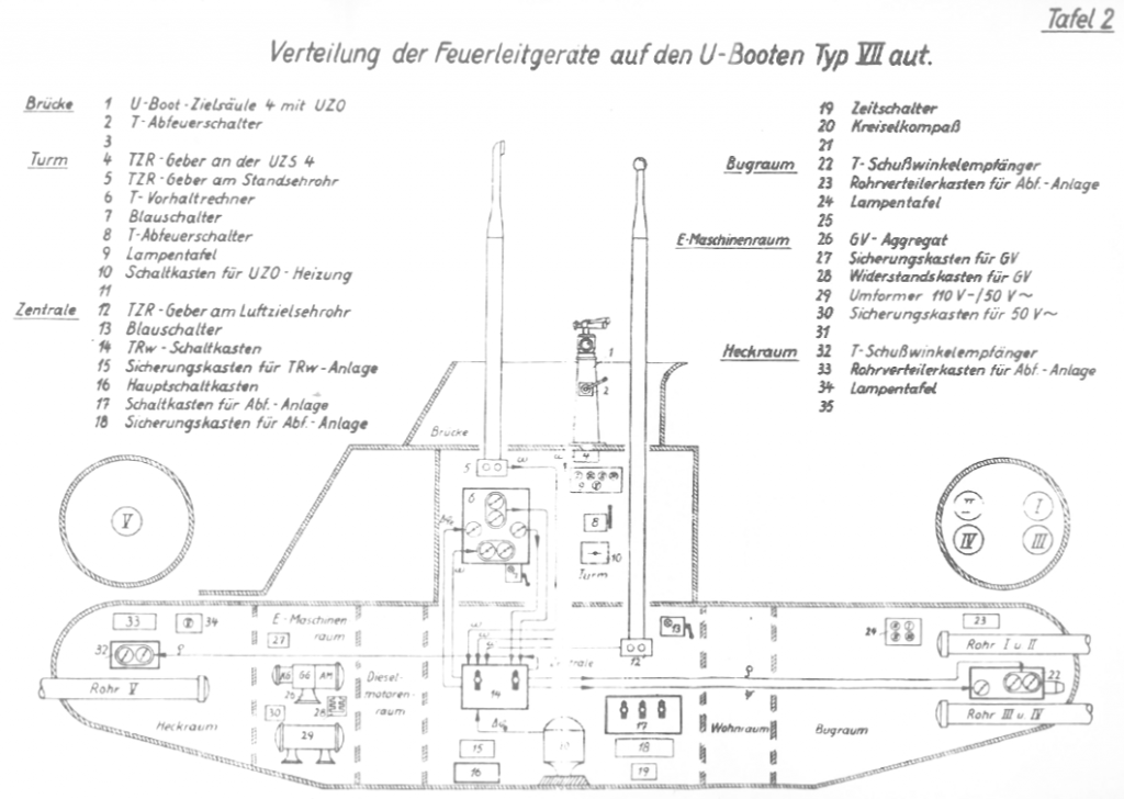
| Bridge: | 1 | The bridge aiming column UZO (U-Boot-Ziel-Optik) |
| 2 | Torpedo launch lever (T-Abfeuerschalter) | |
| 3 | ||
| Conning tower: | 4 | UZO target bearing transmitter |
| 5 | Attack periscope target bearing transmitter | |
| 6 | Torpedo data computer | |
| 7 | Target follow-up switch (Blauschalter) | |
| 8 | Torpedo launch lever (T-Abfeuerschalter) | |
| 9 | Torpedo tubes control lamps | |
| 10 | The UZO heating control box | |
| 11 | ||
| Control room: | 12 | Sky periscope target bearing transmitter |
| 13 | Target follow-up switch (Blauschalter) | |
| 14 | Aiming subsystem control box | |
| 15 | Aiming subsystem fuse box | |
| 16 | Main distribution box | |
| 17 | Torpedo firing subsystem control box | |
| 18 | Torpedo firing subsystem fuse box | |
| 19 | Timing control box | |
| 20 | Gyro-compass | |
| 21 | ||
| Forward torpedo room: | 22 | Gyro-angle receiver (T-Schußwinkelemfänger) |
| 23 | Torpedo firing subsystem distribution box | |
| 24 | Torpedo tubes control lamps | |
| 25 | ||
| E-motor room: | 26 | Rotary machine amplifier (GV-Aggregat) |
| 27 | Gyro-setting subsystem fuse box | |
| 28 | Gyro-setting subsystem control box | |
| 29 | Rotary converter powering the torpedo fire control system | |
| 30 | Aiming and TDC subsystems fuse box | |
| 31 | ||
| Aft torpedo room: | 32 | Gyro-angle receiver (T-Schußwinkelemfänger) |
| 33 | Torpedo firing subsystem distribution box | |
| 34 | Torpedo tubes control lamps | |
| 35 |
Table 3
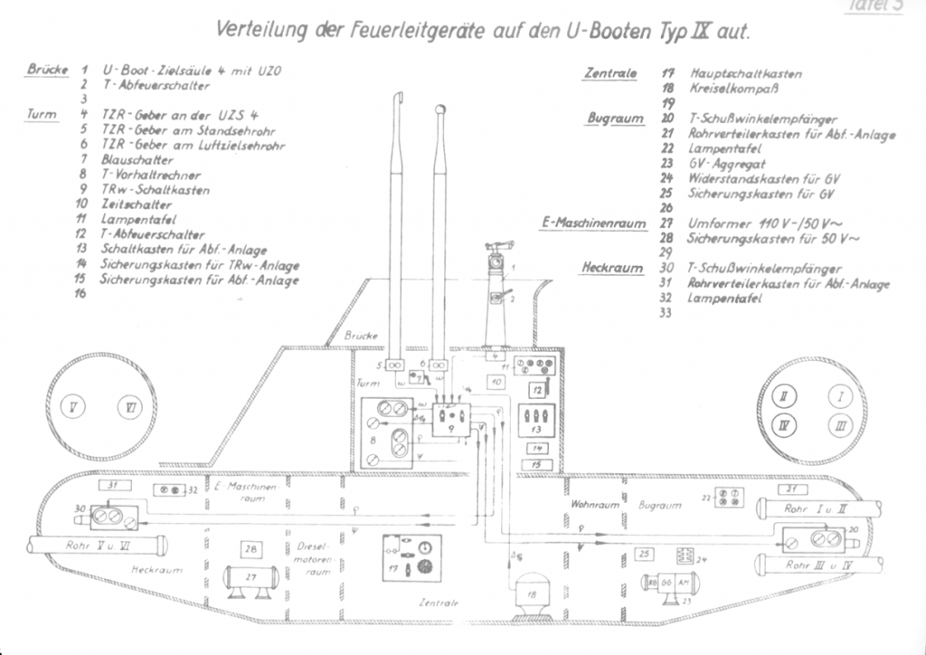
| Bridge: | 1 | The bridge aiming column UZO (U-Boot-Ziel-Optik) |
| 2 | Torpedo launch lever (T-Abfeuerschalter) | |
| 3 | ||
| Conning tower: | 4 | UZO target bearing transmitter |
| 5 | Attack periscope target bearing transmitter | |
| 6 | Sky periscope target bearing transmitter | |
| 7 | Target follow-up switch (Blauschalter) | |
| 8 | Torpedo data computer | |
| 9 | Aiming subsystem control box | |
| 10 | Timing control box | |
| 11 | Torpedo tubes control lamps | |
| 12 | Torpedo launch lever (T-Abfeuerschalter) | |
| 13 | Torpedo firing subsystem control box | |
| 14 | Aiming subsystem fuse box | |
| 15 | Torpedo firing subsystem fuse box | |
| 16 | ||
| Control room: | 17 | Main distribution box |
| 18 | Gyro-compass | |
| 19 | ||
| Forward torpedo room: | 20 | Gyro-angle receiver (T-Schußwinkelemfänger) |
| 21 | Torpedo firing subsystem distribution box | |
| 22 | Torpedo tubes control lamps | |
| 23 | Rotary machine amplifier (GV-Aggregat) | |
| 24 | Gyro-setting subsystem control box | |
| 25 | Gyro-setting subsystem fuse box | |
| 26 | ||
| E-motor room: | 27 | Rotary converter powering the torpedo fire control system |
| 28 | Aiming and TDC subsystems fuse box | |
| 29 | ||
| Aft torpedo room: | 30 | Gyro-angle receiver (T-Schußwinkelemfänger) |
| 31 | Torpedo firing subsystem distribution box | |
| 32 | Torpedo tubes control lamps | |
| 33 |
Table 4
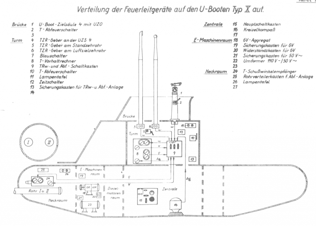
| Bridge: | 1 | The bridge aiming column UZO (U-Boot-Ziel-Optik) |
| 2 | Torpedo launch lever (T-Abfeuerschalter) | |
| 3 | ||
| Conning tower: | 4 | UZO target bearing transmitter |
| 5 | Attack periscope target bearing transmitter | |
| 6 | Sky periscope target bearing transmitter | |
| 7 | Target follow-up switch (Blauschalter) | |
| 8 | Torpedo data computer | |
| 9 | Aiming and torpedo firing subsystem control box | |
| 10 | Torpedo launch lever (T-Abfeuerschalter) | |
| 11 | Torpedo tubes control lamps | |
| 12 | Timing control box | |
| 13 | Aiming and torpedo firing subsystem fuse box | |
| 14 | ||
| Control room: | 15 | Main distribution box |
| 16 | Gyro-compass | |
| 17 | ||
| E-motor room: | 18 | Rotary machine amplifier (GV-Aggregat) |
| 19 | Gyro-setting subsystem fuse box | |
| 20 | Gyro-setting subsystem control box | |
| 21 | Gyro-setting and aiming subsystem fuse box | |
| 22 | Rotary converter powering the torpedo fire control system | |
| 23 | ||
| Aft torpedo room: | 24 | Gyro-angle receiver (T-Schußwinkelemfänger) |
| 25 | Torpedo tubes control lamps | |
| 26 | Tablica lampek kontrolnych wyrzutni torpedowych | |
| 27 |