Basic components of the fire control calculators
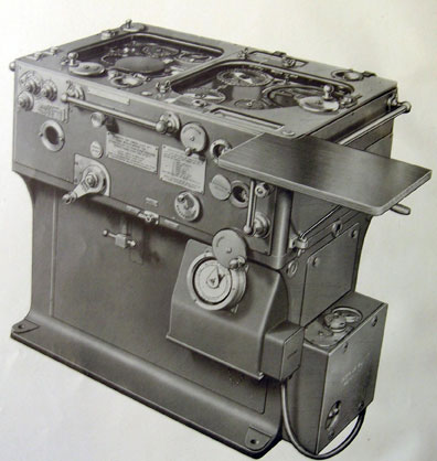
The torpedo calculators that were developed in the inter-war period were progressively more complicated mechanical devices. They evolved from the naval gun fire control systems (such as the Dreyer Fire Control Table and the Admiralty Fire Control Table or Argo Clock). The torpedo fire control problem was simpler due to being restricted to two dimensions than the gun fire control problem and torpedo ballistics are much simpler than gun projectile ballistics.
These calculating instruments will be called calculators because as opposed to computers, they were designed to solve only one problem and the implemented algorithm was determined by the instrument's construction (that is it cannot be changed without modifying the calculator). The mechanical calculators consisted of many basic mechanisms which were responsible for performing basic mathematical operations. These mechanisms were connected together to implement mathematical equations that modeled the movement of gun projectiles or torpedoes. When the whole mechanism gets into the balanced state, it means that the solution was found. Some of these basic mechanisms were presented in a training movie which was released in 1953 by the United States Navy. The mechanisms are presented in the context of gun and anti-aircraft fire control calculators, but it is also relevant to torpedo calculators.
A few comments on the movie: in the part describing cams, an important issue is presented – the cam generates an output value for every input value. In other words, the input as well as output values are continuous. The mechanical fire control calculators were in fact analog calculating instruments as opposed to digital computers using discrete values.
Considering the functions of the mechanisms presented in the movie, comparisons naturally arise with their equivalents in digital computers.
The equivalent of shaft transferring values are data buses, the equivalent of constant ratio gears with a ratio other than 1:1 (that means dividing or multiplying by a constant) is the logical shift right or left.
The equivalent of the differential gear is a digital arithmetic unit implemented as a combinational logic circuit.
The cams can be considered as function value generators or as the tables of pre-calculated values stored in ROM memory which are addressed by input data.
The equivalent of a multiplier is a digital arithmetic unit implemented as a combinational logic circuit.
The integrators in digital computers are implemented in software using numerical integration algorithms. Components solvers are similar.
The bevel differential gears presented in the movie were constructed on the basis of bevel gears and were quite large. Therefore, jeweled differential gears were often used as they were much more compact.
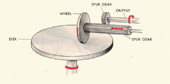
In the movie an integrator was presented where the movement of the disc was transferred to the roller by means of a gear with a constant ratio of 1:1 which consisted of two balls held in a movable carriage. Very often simpler integrators were used where the ball gear was eliminated and the output roller was driven directly by the disc. In both versions of integrator the operating principle was the same, the main difference was greater friction in the simpler variant, which restricted the speed of operation. Therefore, this simpler variant was used when the rate of change was small – i.e. in the torpedo fire control calculator. The more complicated but faster integrators with the ball gear were used in the gun and anti-aircraft fire control calculators.
Below a few more basic mechanisms are described that were not presented in the movie but were also commonly used in fire control calculators.
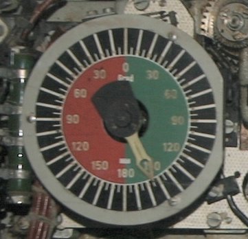
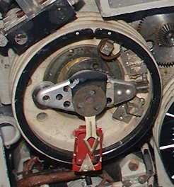
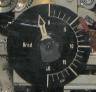
The dials were used to show numerical values. They can be used while entering data into the calculator as well as to present the results of calculations. Generally, dials were of two types:
- fixed dial and trainable pointer. This type of dial could be implemented in two ways:
- the pointer rotates along the axis placed in the center of dial
- the pointer is placed on the trainable ring, which is around the edge of dial - trainable dial and fixed pointer. This type of dial also can be realized in two ways:
- the dial rotates along the axis placed in the center
- the dial as a rotating ring
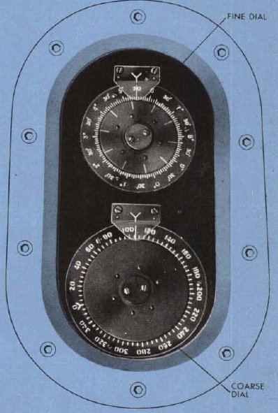
When there is a need to show some value with great accuracy (i.e. while entering target course), the two dials – fine and coarse (Germ. fein/grob) are used. They are geared with themselves in such a way that their pointers (or dials) rotate like the minute and hour pointer of a clock. When the fine pointer (or dial) makes one turn, the coarse pointer (or dial) makes only part of a turn. Most of the course dials were constructed so that the coarse dial is scaled every 5° and its full range is 360°. The fine dial is scaled every 5‘, and its full range is 10°. The input shaft which enters the value is connected with the fine dial and the rough dial is driven from the fine dial by means of gear with the ratio 1:36.
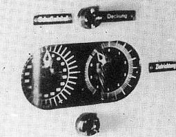
The double indicator is a slightly different course indicator that consists of a rotating inner dial and a rotating outer ring. The rotating ring is scaled every 10° and its full range is 360°, and the inner dial is scaled every 1°, and its full range is 10°.
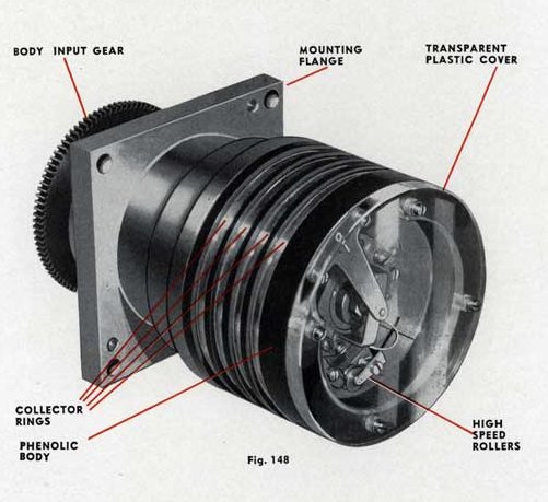
The other mechanisms used in fire control calculators were servomechanisms. Many components of the calculator (i.e. multipliers and integrators) did not have sufficient output power to drive other components. Because of the mechanical construction of the calculator, all gears and bearings generate losses which disperse part of the power which should be used for driving mechanisms. Therefore, servomechanisms are used which increase the output power of components if necessary. The servomechanism is used as follows: the output shaft of the calculating component (i.e. multiplier) does not directly drive other calculator components, but controls the electric motor of the servo which follows the movement of the output shaft. The additional power is introduced to the calculator by means of electrical energy powering the servo's motor.
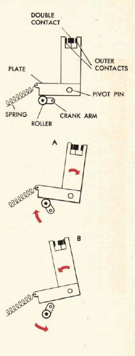
The servomechanism consists of an electric motor, differential gear and a control unit. The shaft of the motor is the output shaft of the whole unit: calculating component – servomechanism. One of the differential gear shafts is driven by an electric motor. This shaft is also the output shaft of the whole unit. A second shaft of the differential gear is driven by the output shaft of the calculating component. The differential gear on its output generates an error signal – the difference between the position of the calculating component output shaft and the position of the electric motor. On the output shaft of the differential gear is a cam which triggers the contacts that control the electric motor. Depending on the sign of the error signal (that is the direction of the rotation of the differential gear output shaft), the contacts turn the electric motor in the corresponding direction. The electric motor rotates the shaft and seeks to decrease the difference between the output value of the calculating component and the value represented by the electric motor shaft. When the electric motor shaft rotates by the same value as the output shaft of the calculating component, the error signal would equal zero and the control cam would find the neutral position where the electric motor would be shut off.
The control unit which controls the electric motor can be implemented in many ways. One of them uses an electric induction motor which consists of two windings alternatively working as starting and main winding depending on the position of the control contacts. The main advantage of this solution is simplicity – the main disadvantage – the necessity of having an alternating current power supply.
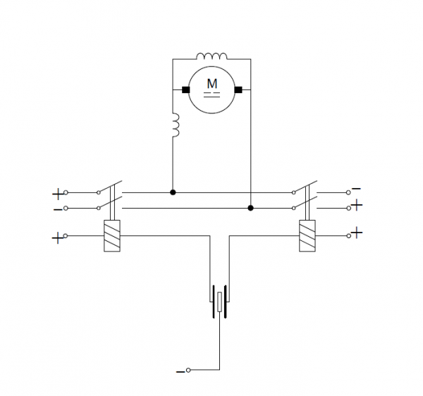
A shunt or compound direct current motor controlled by relays can also be used. The main advantage is being powered by direct current voltage, the disadvantage - complexity which results in susceptibility to failures and quite large size.
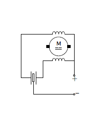
An intermediate solution could be using a modified compound direct current motor that consists of two field windings which create magnetic fields of opposite directions. Depending on the contact position, the current flows only through one of these windings. The complexity of such a solution is comparable to the first one, but there is no need to have an alternating current supply. However it is necessary to have a non-standard electric motor.
The follow-up nature of the servomechanism is used in another important component of the calculator – the electro-mechanical comparator. Comparators are necessary while implementing circuits solving equations. They create an error signal which – in the feedback loop – influences the equation's variables, seeking to balance both sides of the equation – that is solving it. This function can be realized by the differential gear, those two input shafts are provided with the values of both sides of the equation. The output of the differential gear by means of the cam, controls the contacts which in turn control the electric motor which changes one of the equation's variables.
It seems, that this type of comparator was used in the German torpedo calculator developed by Siemens.
Comparators were used in the American fire control calculators that compared the relative position of the movable roller and the drum. This construction was called follow-up heads.
An example of comparator usage is the implementation of the divider unit which consists of an integrator and a comparator. The integrator utilizes the following features: the amount of rotation of the output roller of the integrator during a single rotation of the disc depends on the position of the ball gear – its distance R from the center of the disc – and is equal to 2*π*R. The distance R depends on one of two input values of the integrator (the second one is the disc rotation). The input values responsible for ball gear shifting, disc rotation and output value respectively are designated X1, X2 and Y, so it can be seen:
Y = 2*π*X1*X2
Using this formula, the integrator can be used to implement a multiplier function. The constant factor 2*π can be easily eliminated by using the appropriate constant gear ratio on the output shaft of the unit.
By connecting the comparator, the divider function can be implemented.
The value X1 (divider) is provided to the input of the integrator. The second input of the integrator is driven by the output shaft of the electric motor controlled by the comparator. The value presented by this input is X2 - quotient. The output of the integrator Y is equal to 2*π*X1*X2. This output is connected with one of the comparator inputs. The other input of the comparator is provided with the dividend.
When dividing value A by value X1, the input of the comparator is provided with the value A, while one of the integrator's input – value X1. On the output of the divider unit is the value Y = 2*π*X1*X2. The comparator compares the given value A (dividend) and generates a signal that controls the electric motor which turns the shaft changing value X2. The electric motor keeps turning till the moment of equalization of value Y with value A. Then the electric motor shaft represents value X2, which is the result.
A comparator can be embedded with a doubled dial. The comparing of values can then be monitored visually and in the case of a control unit or electric motor failure, due to coupled hand wheels, the comparison can be done manually.
References:
[1] Dreyer Table Mark I
[2] Handbook of The Admiralty Fire Control Clock Mark I and I*
[3] Basic Fire Control Mechanisms - Section 2 - Mechanical Units
[4] Harvey G. Cragon, The Fleet Submarine Torpedo Data Computer
[5] Basic Fire Control Mechanisms - Section 3 - Electromechanical Units
[6] Basic Fire Control Mechanisms - Section 6 - Arma Mechanisms


