
")
Development of torpedo fire control systems for the Kriegsmarine
As a result of the Treaty of Versailles, which was signed in 1919, Germany was not allowed to possess submarines or to develop torpedo technology. However, in July 1922, a company was created in the Netherlands called Ingenieurskantoor voor Scheepsbouw where German engineers designed and constructed submarines for foreign countries, gaining experience which was utilized later when restoring the German submarine arm – the U-Bootwaffe. In 1919, the German Naval High Command funded a Torpedo Experimental Station in Eckernförde (Torpedoversuchsanstalt (TVA) Eckernförde), which officially was tasked with maintaining and servicing torpedoes that were left in storage after WWI. In fact, the Station led the effort to develop the wet-heater G7a torpedo and the electric G7e torpedo, among the others.
Provisions of the Treaty of Versailles allowed Germany to possess a few pre-dreadnoughts and cruisers. These warships were equipped with torpedo tubes, and hence torpedo fire control equipment. There were the: BNZA 1 – Brücke Nacht Ziel Apparat 1 – torpedo director located at the command station fitted with open sights and the RZA – Rohr Ziel Apparat 1 – torpedo sight located at the torpedo tubes fitted with a telescope. Using the BNZA 1 (on the basis of estimated angle on the bow and target speed) a deflection angle was calculated which was passed to the operators of the torpedo tubes where they set the received angle on the RZA aimer and trained the tube so that the target was near the aiming line. Finally, the vessel started its turn and the torpedoes were launched when the target crossed the sight line.
In mid-1927, a committee was created at the TVA which was tasked with developing torpedo fire control systems, but due to a lack of funds very little progress was made. In 1928 the following items were designed: a new torpedo director the BNZA 2, a new target bearing column the TRW 28 (Torpedo-Richtungsweiser) and a torpedo calculating disc.
BNZA 2 was an improved version of the BNZA 1, with the added ability to set the angular speed of turn correction (Germ. Winkelgechwindigkeit) and the order delay correction (Germ. Befehlsverzug).
The target bearing column TRW 28 was used as an aiming device. It was located on the command platform of the warship (or there were two columns on both sides of the platform in the case of larger ships). It was fitted with a telescope. When aiming with the column, the following values could be set: salvo spread angle, angular speed of turn correction, order delay correction, direction of the torpedo tube, and deflection angle determined by the calculation disc. The target bearing column could also transmit the target bearing to the operators of the calculating disc who determined the deflection angle.
The calculating disc was 0.5 meters in diameter and was located near the target bearing column. To determine the deflection angle (Germ. Vorhaltwinkel) the target speed and angle on the bow had to be set. Additionally, the current target bearing had to be set, thus allowing the torpedo tube operators to train them correctly relative to the sight line of the TRW. After performing the calculations and training the torpedo tubes, the warship started its turn and the torpedo tube operators launched the torpedoes when the torpedo officer who operated the TRW issued the order. The length of the torpedo run was determined from tables and compared with the maximum range of the torpedo to determine if target is in range.
The launching of a salvo was done in the following way – after launching the first torpedo, the torpedo officer pressed the bar on the TRW which released a spring which turned the telescope by the salvo spread angle which was set previously. When – as the result of the ship turning – the target again was in the sight line, the next torpedo was launched. This procedure was repeated until firing the whole salvo had been accomplished.
A plot was used to determine the target’s course parameters. The dedicated plot room contained the plot table and the set of synchro receivers which showed: own course (from the gyro-compass), own speed (from log), distance to the target (from the rangefinder station) and the target bearing (from the target bearing column TRW or torpedo director BNZA) and a clock. The operators on the basis of the received data plotted the target’s course, and then determined its speed and the angle on the bow.
In time, the development of a new torpedo firing method called Auswanderungsverfahren which used the rate of change of bearing theory was begun.
As mentioned earlier, the Auswanderungsverfahren method was derived from the Ausdampfverfahren method. This latter operated on the premise that in the case of two objects being on a collision course (let's assume that these are the torpedo and the target), the target bearing taken from the torpedo is constant.
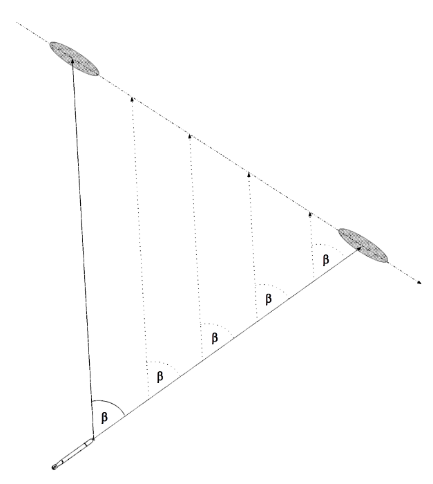
Drawing 1. Constant target bearing in the case of objects being on a collision course
The Ausdampfverfahren method is based on the fact that through adjusting own ship course and speed, the target bearing ω was made constant (that means that own ship and the target were on a collision course). That means, that the linear displacement (that is the displacement's component which is perpendicular to the bearing line) of own ship is the same as the linear displacement of target.
BF = ED
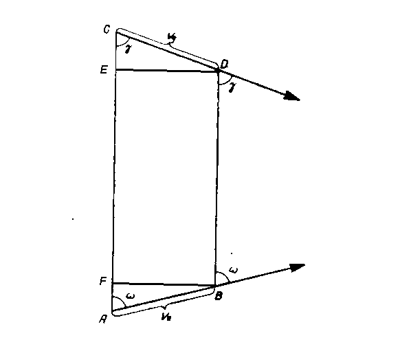
Drawing 2. The principle of the Ausdampfverfahren method [1]
Knowing own speed ve and target speed vg as well as the target bearing ω and angle on the bow γ the following formula can be derived:
\[\begin{aligned} \frac{BF}{v_e} = sin ω \text{ and } \frac{DE}{v_g} = sin γ \end{aligned} \]
that is
\[\begin{aligned} BF = v_e * sin ω \text{ and } DE = v_g * sin γ \end{aligned} \]
Because the linear displacements are the same:
\[\begin{aligned} v_e * sin ω = v_g * sin γ \end{aligned} \]
The sines law applied to the torpedo triangle is as follows:
\[\begin{aligned} v_t * sin β = v_g * sin γ \end{aligned} \]
Two last equations can be compared, which gives the result:
\[\begin{aligned} v_t * sin β = v_e * sin ω \end{aligned} \]
that is
\[\begin{aligned} sin β = \frac{v_e}{v_t} * sin ω \end{aligned} \]
As can be seen, the deflection angle β can be determined on the basis of three values which are known accurately – torpedo speed vt, own speed ve and target bearing ω. There is no need to use estimated or measured values for target speed vg and angle on the bow γ.
On the torpedo director the target speed was set to the own speed and angle on the bow to the target bearing.
The main advantage of the Ausdampfverfahren method was using two values which were known with great accuracy without the need to take distance measurements. The main disadvantage was the long time (up to twelve minutes) needed for own ship maneuvers to adjust own speed and course to make the target bearing constant.
The Ausdampfverfahren method was modified to eliminate the disadvantages mentioned above. The derived method was called Auswanderungsverfahren (so called version B). The two target bearings had to be taken in the short time interval and one distance measurement had to be taken. There was no need to maneuver with own ship. On the basis of measured results and own speed, the linear displacement of the target (that is the target speed component which was perpendicular to the target bearing line) was calculated.
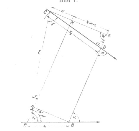
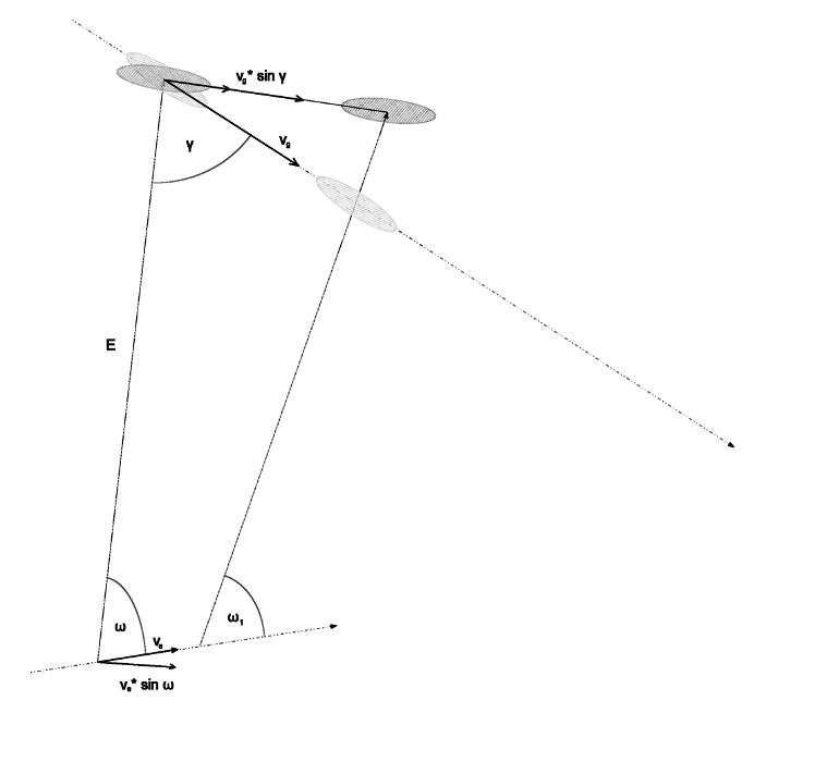
Drawing 3. The principle of the Auswanderungsverfahren method [1]
On the drawing, the own ship is cruising on a course crossing points A and B. The target cruises on a course crossing points C and D. The target bearing in point A is ω and in point B - ω1. The difference of the bearings - ω - ω1 = ε. From point C there is a line drawn, that is perpendicular to the prolongation of the BD line (segment CG), from the point A – line parallel to the line BD. Segment A1B which is parallel to segment CG is also created. The linear displacement of the target is equal to:
\[\begin{aligned} CG = v_g * sin γ_1 \end{aligned} \]
The segment CG can be divided into two parts: CH i GH.
CH = E * sin ε
\[\begin{aligned} GH = v_e * sin ω_1 \end{aligned} \]
So:
\[\begin{aligned} CG = CH + GH = E * sin ε + v_e * sin ω_1 = v_g * sin γ_1 \end{aligned} \]
The component E * sin ε is added or subtracted depending on whether the second bearing is greater or less than the first.
The law of sines applied to the torpedo triangle looks like the following:
\[\begin{aligned} v_t * sin β = v_g * sin γ_1 \end{aligned} \]
Comparing two last equations we get:
\[\begin{aligned} v_t * sin β = v_e * sin ω_1 ± E * sin ε \end{aligned} \]
that is
\[\begin{aligned} sin β = \frac{v_e * sin ω_1 ± E * sin ε}{v_t} \end{aligned} \]
A torpedo attack using the Auswanderungsverfahren method was performed as follows: the distance to target was measured and the first target bearing was taken. Knowing own speed, using the calculating disc, the value ve * sin ω1. was determined. After 1 minute elapsed, the second target bearing was taken, the bearing difference was calculated and using distance measured before, the component E * sin ε was calculated. Both calculated values were added and the result was set on the torpedo director as target speed. The angle on the bow was set to 90°.
From experience it was known that the best firing results (that is values set on the director correspond to the real values) occurred when torpedoes are launched 10~15 seconds after the second target bearing. When this time was longer, the calculated values became less accurate. The usage of the described Auswanderungsverfahren method was constrained only to the line of battle situation. When there was a crossing the T situation, the change of bearing is much greater, so the component E * sin ε is also greater, which results in a greater final error. Thus this method was modified in such a way that it could also be used in a circular fight. The modification was related to the measurement of rate of change of bearing (or angular speed of the target) instead of measuring bearings and then calculating the difference. The change of bearing could be presented as the differential
\[\begin{aligned} \frac{dω_N}{dt} \end{aligned} \]
or ωN in short.
The differential means that the change of bearing takes place in such short time that the path covered by the target (segment AB) can be approximated by the angular change of the bearing (arc AC).
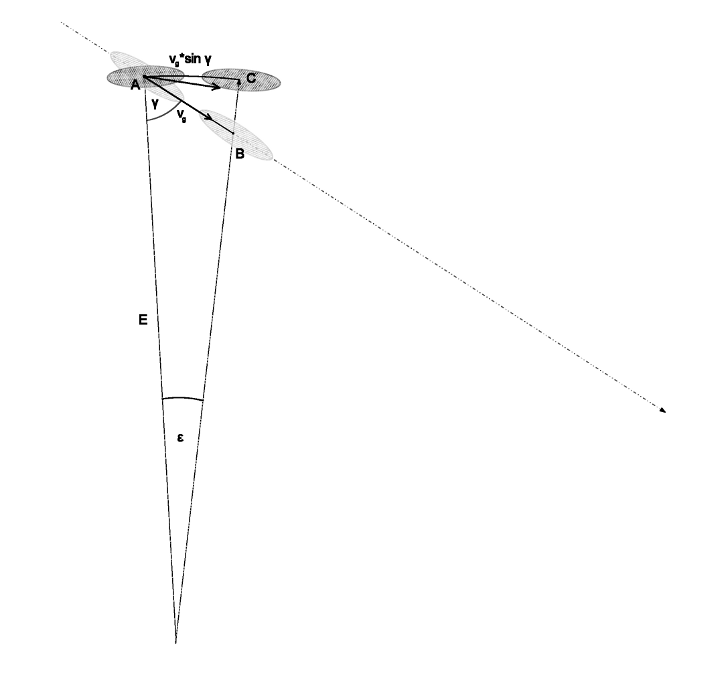
Drawing 4. Differential of bearing change
Angle ε (as an arc measurement) is equal to
\[\begin{aligned} ε = \frac{AC}{E} \end{aligned} \]
Assuming that own ship is stationary, the angular speed equals
\[\begin{aligned} \frac{ε}{dt} = \frac{AC}{E * dt} = ω_N \end{aligned} \]
Target moves at speed vg and with the angle on the bow γ. So the target speed component perpendicular to the bearing line has the length
\[\begin{aligned} v_g * sin γ = \frac{AC}{dt} \end{aligned} \]
So
\[\begin{aligned} ω_N * E = v_g * sin γ \end{aligned} \]
It should be noted that the above relationships are valid only for short time intervals because both angular speed and angle on the bow are not constant, but depend on the bearing.
The law of sines for the torpedo triangle looks as follows:
\[\begin{aligned} v_t * sin β = v_g * sin γ \end{aligned} \]
Therefore (assuming own speed equals zero) comparing the two last equations we get:
\[\begin{aligned} v_t * sin β = ω_N * E \end{aligned} \]
The product of angular speed and distance was set on the torpedo director as target speed, the angle on bow was set to 90°.
The above relationships are valid only when own ship is stationary. When own ship cruises with some speed, the rate of change of bearing consists of – apart from the target movement – own speed movement.
Drawing 5. Target bearing when own speed is non-zero
In this case, the measured rate of change of bearing is a “relative” value which is the sum (or difference) of target and own ship speed components perpendicular to the bearing line. So as a result we get:
\[\begin{aligned} ω_N * E = v_g * sin γ ± v_e * sin ω \end{aligned} \]
after inserting the law of sines applied to the torpedo triangle:
\[\begin{aligned} v_t * sin β = ω_N * E ± v_e * sin ω \end{aligned} \]
that is:
\[\begin{aligned} sin β = \frac{ω_N * E ± v_e * sin ω}{v_t} \end{aligned} \]
That means that to calculate deflection angle, five values are need, of these four (ωN, ve, ω, vt) are known accurately, and the fifth value - distance E can be measured relatively easily. The task of determining deflection angle – because of the quite complicated calculations – had to be performed by a mechanical computer. In the beginning of the 30s, a few German companies were contracted to develop such a device.
One of the main problems was the need for accurate measurement of the rate of the change of bearing. When the distances were about several kilometers and relative speed twelve knots (assuming opposite courses), the rate of change of bearing was twelve degrees per minute. But when own ship and target cruise the same course and direction, the rate of the change of bearing was several degrees per minute. A measurement as simple as taking two bearings in a short time interval would be very inaccurate. For that reason, German companies Zeiss and Kreiselgeräte GmbH received the task of creating equipment for accurate measurement of the rate of change of bearing.
Meantime, the TVA started a design study for an instrument that would calculate the salvo spread and order delay correction. Till then, these values were taken from the tables.
From the beginning of 1929 the telescopes were exchanged for binoculars in all sighting instruments. The TVA started its own development of the device to measure the rate of change of bearing. Unlike the device developed by Kreiselgeräte GmbH, which used the output of the main gyro-compass, the TVA adapted the gyro from the G7v torpedo to the role of rate gyro (Germ. Wendekreisel). In the case of the rate gyro, the precession is proportional to the angular speed of the gyro turn. The angular speed can be determined by measuring the precession.
In 1930 it became clear that neither Zeiss, nor Kreiselgeräte GmbH, nor TVA were able to build an instrument for measuring the rate of change of bearing. The High Command of the Reichsmarine ordered Zeiss to continue the research, but this time, they had to be supported by Kreiselgeräte GmbH and TVA. Also in 1930, a torpedo fire control room (Germ. Torpedo-Rechenstelle) was designed for the newly ordered heavy cruisers of the Deutschland class (Deutschland/Lützow, Admiral Scheer and Admiral Graf Spee). This room was equipped with the following instruments: torpedo calculating disc designed by TVA, torpedo salvo spread calculator, order delay calculator, plotter, and synchro transmitters for transmitting the deflection angle to the torpedo tubes.
The new plotters (Germ. Koppelanlage, Koppelgerät) made plotting and determining target course parameters easier. These were semi-automatic devices (Germ. halbautomatische Koppelanlage), which on the basis of data received from the log and gyro-compass, automatically calculated the distance covered in the north-south and east-west directions. The counters which showed the covered distances were located near the plotting table, on which operators – at the same time intervals (30 seconds or 1 minute) marked the own ship position. Moreover, near the plotting table, synchro receivers were located which were used for transmitting the target bearing and distance to the target. Using this information the target position relative to the own ship position was marked.
Because the method of launching a torpedo salvo used until then required own ship turning and rotating the torpedo sight by the calculated spread angle, it was quite inaccurate. The TVA attempted to modify the gyro of a G7v torpedo to make it turn after leaving the tube (gyro-angled torpedoes).
The target bearing column TRW 28 was integrated with the torpedo calculating disc and received the designation TRW 30.
By 1931 there was still no successful development of a rate of change of bearing measurement instrument and the Anschütz Company was added to the group of companies working on this device. The device in design was designated the TAm (Germ. Torpedo-Auswanderungsmesser). Depending on the company, it had an appropriate suffix:
- Anschütz - TAm 3
- Goerz - TAm 4
- TVA - TAm 5
In the same year, Zeiss designed a fully-automatic plotter (Germ. vollautomatische Koppelanlage, Torpedo-Gefechtsschreiber), which on the basis of data from the log, gyro-compass, rangefinder and target bearing, automatically plotted the position of own ship and target, as well as the calculated target course and speed.
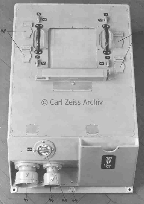
Photo 1. Automatic plotter manufactured by Zeiss [2]
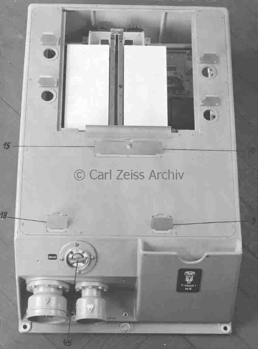
Photo 2. Automatic plotter manufactured by Zeiss [2]
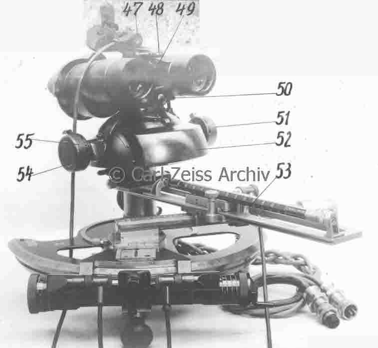
Photo 3. Torpedo director BNZA fitted with 8x60 binoculars [2]
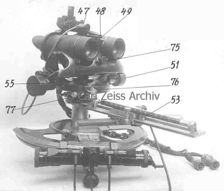
Photo 4. Torpedo director BNZA fitted with 8x60 binoculars [2]
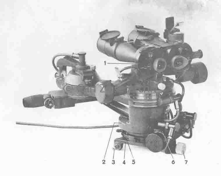
Photo 5. Torpedo director RZA fitted with 7x50 binoculars [2]
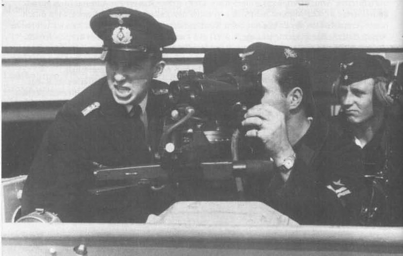
Photo 6. The operators of the torpedo director on the deck of a German warship [3]
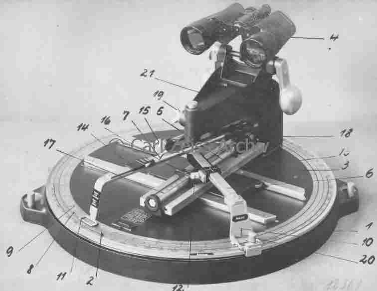
Photo 7. Torpedo calculating disc fitted with 7x50 binoculars [2]
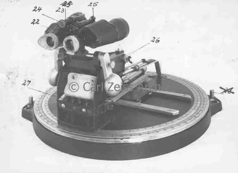
Photo 8. Torpedo calculating disc fitted with 7x50 binoculars [2]
Because the TVA was unsuccessful in the development of gyro-angled torpedoes, they developed a gyro-based salvo shooting instrument (Germ. Fächergerät). It operated as follows – after introducing the salvo spread angle, the warship started its turn and the torpedo officer launched the first torpedo. The subsequent torpedoes were launched automatically when an electrical circuit was completed by a gyro which was stationary relative to the earth (the ship was turning).
Finally only TAm 5 was developed enough to begin its production and installation on ships. The devices created by Anschütz and Kreiselgeräte GmbH were abandoned.
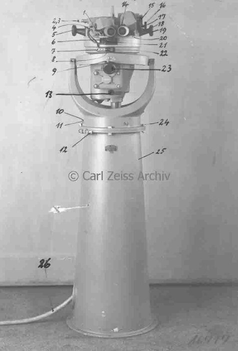
Photo 9. Torpedo-Auswanderungsmesser developed by Zeiss [2]

Photo 10. Torpedo-Auswanderungsmesser developed by Zeiss [2]
In 1933 the heavy cruiser Deutschland (later renamed to Lützow) was commissioned. It was fitted with the earlier mentioned torpedo fire control room supplemented with following equipment:
- sighting instruments: two TRW 30 columns on each side of the command station, two BNZA 3 torpedo directors located on the forward command platform, one TAm 5 column located on the upper command platform;
- rangefinders: two 3-meter rangefinders located on both sides of the combat station.
The torpedo fire control room, which was located under the main deck, contained the following equipment: torpedo calculating disc, parallax correction calculator, salvo spread angle, automatic plotter and synchro transmitters which transmitted the calculated deflection angle to the torpedo tubes. The torpedo tubes were fitted with RZA 4 sights.
The TRW 30 columns – after being integrated with the torpedo calculating disc – were improved to include parallax, angular speed of turn and order delay correction. However, in fact – it was still the model from the year 1928 with extended functionality and it had become overcomplicated and complex to operate. Therefore, an order was placed with the Siemens company to develop a new instrument from scratch (designated TRW 34), which had to contain all of those functions. This development was completed in 1935. Additionally it could measure the rate of change of bearing like the Tam columns, but instead of the rate gyro, the electric motor driving the binoculars was used. The operator of the TRW column tried to adjust the motor speed so as to keep the target in the crosshairs of the binoculars - the adjusted speed of the motor was well known.
In 1934 the TVA begun development of the next version of the TAm 6. It was found that the TAm 6 column made such accurate rate of change of bearing measurements that the torpedo calculating disc introduced too large an error into the calculation process. That's why Siemens developed an electromechanical torpedo calculator (Germ. Torpedo Schuss Rechner 1 – T. Schu. Re. S. 1.), which in connection with the TAm 6 column calculated the angle on the bow, target speed, deflection angle, parallax correction and maximum distance to the target at the moment of launch.
Because the Siemens Company was not able to manufacture enough of these calculators, these instruments were also ordered from the Zeiss Company under the designation T. Schu. Re. Z. 1.
In 1933 the new wet-heater torpedoes of the G7a type entered service. Almost three years later – at the beginning of 1936 – the development of gyro-angle setting gear for torpedoes was completed. From then on, a torpedo salvo could be launched by setting a slightly different gyro-angle on each torpedo rather than turning the whole ship.
In mid-1935 the first U-Boats of the restored U-Bootwaffe were commissioned. These were type IIA U-Boats – small submarines with a displacement of 250 tons, armed with three bow torpedo tubes. Soon after – in 1936 – two type IA U-Boats with four bow and two stern torpedo tubes were commissioned. In the initial period of their service, the torpedoes were not able to turn after leaving the tube. To calculate deflection angle the tables and the torpedo calculating disc were used. Aiming was done by periscope (during a submerged attack) or sight column TUZA 1 (Germ. Torpedo-U-Boot-Zielapparat) – while attacking on the surface. The sight column TUZA 1 transmitted the target bearing to the control room by means of the Bowden cable. An attack with this set of instruments was conducted as follows: first, the target course parameters were determined (on the basis of a plot or by estimating). In the control room, the torpedo officer read the target bearing from the mechanical receiver (in the case of the sight column) or directly from the periscope scale and on the basis of this information and knowing own and target course he calculated the angle on the bow. Then, by means of tables or using the torpedo calculating disc, the deflection angle was determined and transmitted verbally to the bridge – to the officer who operated the sight column or to the commander at the periscope. After setting the deflection angle on the sight column or periscope, the U-Boat was turned to get the target in the crosshairs of the sight or the periscope. Then the launch order was passed to the bow torpedo room where the torpedo mate manually triggered the torpedoes. A salvo of torpedoes was launched by firing torpedoes while the U-Boat was turning. The obvious disadvantage of such a system was the long delay between passing the target bearing to the control room and receiving the deflection angle – especially when using the sight column on the bridge. Therefore the Zeiss Company was ordered to develop an improved sight column, which – apart from transmitting target bearing to the control room – could determine the deflection angle. The completed instrument was called TUZA 2 and was similar to the BNZA torpedo director used on surface vessels. The sight included the torpedo triangle, which – apart from calculating deflection angle – allowed it to calculate the maximum distance to the target while incorporating the correction for angular speed of turn. The main disadvantage of this sight (as in the case of TUZA 1) was the necessity to demount the instrument before submerging the U-Boat. Therefore Zeiss developed a new version – TUZA 3 – which was pressure-proof up to a depth of 100 meters.

Photo 11. TUZA 2 – torpedo sight integrated with the torpedo triangle [2]
In 1936 the first type VII U-Boats entered service. As mentioned earlier, the problem of gyro-angling torpedoes was also resolved that year. In the case of surface vessels equipped with trainable torpedo tubes (with the exception of torpedo boats) the gyro-angled setting was used mainly to launch accurate torpedo salvos (without turning the ship). In the case of submarines, which were mainly fitted with fixed torpedo tubes, gyro-angled torpedoes increased attack flexibility, making maneuvering the whole U-Boat unnecessary.
To fully utilize this feature, an appropriate fire control system had to be developed that would make possible:
- fast deflection angle calculation (taking into account the parallax correction)
- fast gyro-angle setting at the torpedo
- remote torpedo launch by the commander or torpedo officer
In 1936 a calculator designated Torpedovorhaltrechner C/36 was developed by Siemens. This device, on basis of following inputs: target speed, distance to the target, angle on the bow and target bearing, calculated: maximum distance to the target, deflection angle, parallax correction and gyro angle, which was transmitted by synchro links to the torpedo rooms. The calculator calculated solution only for torpedoes running with speed of 30 knots. The salvo spread angle was calculated by separate device (Torpedo-Streuwinkel-Rechner) developed by TVA. The calculator C/36 was installed on 10 type VIIA U-Boats (U 27 - U 36).
In 1937 on 11 type VIIB U-Boats (U 45 - U 55) was installed the improved version of the type C/36 calculator. To the calculator C/37 the torpedo speed could be entered.
In 1939 a calculator designated T. Vh. Re. S2 manufactured by Siemens entered service. Moreover, instead of the sighting column TUZA 3 a new sighting column designated UZO (U-Boot-Ziel-Optik) 1 developed by Zeiss was installed. These columns were not embedded with the torpedo triangle, but featured electrical transmission of the target bearing to the torpedo calculator by means of a synchro link. Zeiss binoculars of the type UDF 7x50 were used as the sighting device. When TUZA columns were exchanged for the UZO 1 columns on the type IX U-Boats, it was found that the UZO 1 column was not tall enough to see over the bridge casing. So in the case of these U-Boats, the column was installed with an additional base and this version was designated UZO 2. Because the sighting binoculars of the UZO 1 and UZO 2 columns were not water-resistant and pressure-proof, they had to be dismounted before every dive. The mountings for the UZO binoculars were constructed such that when needed (in the case of a torpedo calculator malfunction) the TUZA 3 sight with torpedo triangle could be installed.
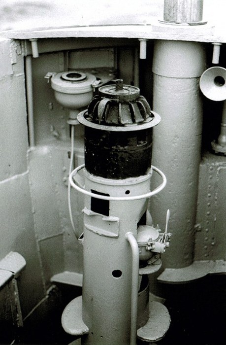
Photo 12. UZO sight column on the bridge of U 995
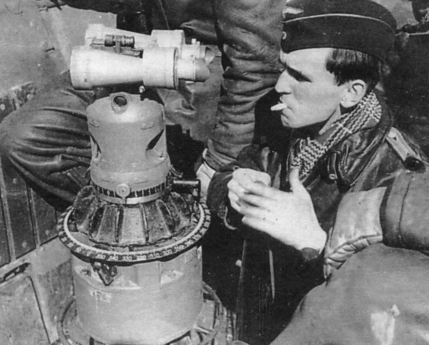
Photo 13. Upper part of UZO sight column with the UDF 7x50 binoculars on the bridge of U 86 [4]

Photo 14. Upper part of UZO sight column with the UDF 7x50 binoculars
fitted with open sight for rough aiming [2]
The torpedo gyro angle calculated by the torpedo calculator was transmitted to receivers in the torpedo rooms by means of a synchro link. The torpedo tube operators manually set the gyro angle at the torpedoes, trying to match the indicators of the torpedo gyro-setting gears and gyro-angle receivers connected to the calculator.
In 1940 a new system was developed which incorporated synchro links and rotary amplifiers that made possible automatic setting of the gyro angle at the torpedoes without human intervention. Moreover, all parts of the fire control system were standardized to make it possible to install them on every type of U-Boat. Therefore, training time was shortened when the uniform fire control system was used on all types of U-Boats.
Another version of the electromechanical torpedo calculator designated T. Vh. Re. S3 was developed which (compared with version S2) additionally calculated the salvo spread angle and incorporated the automatic gyro angle setting system mentioned earlier. This system was also fitted with a delay circuit which allowed launching subsequent torpedoes in a salvo at a time interval of 2-3 seconds.
Another improvement was a water-tight and pressure-resistant torpedo launching lever designed by Siemens located on the bridge. Till then, the torpedo launching button was located in the control room, and in the case of a surface attack – when the torpedo officer was on the bridge – the button was operated by means of a Bowden wire.
The torpedo calculator T. Vh. Re. S3 completed trials conducted by TVA and was fitted on the front-going U-Boats from mid-1941 on.
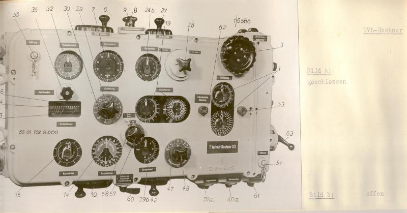
Photo 15. Torpedo calculator T. Vh. Re. S3
As the result of standardizing torpedo fire control system components, it now consisted of the following main elements: torpedo calculator T. Vh. Re. S3, gyro-angle receiver for the bow torpedo tubes (which allowed setting the gyro-angle for the four bow torpedo tubes), and two versions of the gyro-angle receiver for the stern torpedo tubes –one for the single tube on type VII U-Boats and the other for two torpedo tubes on the type IX and XB U-Boats.
In the following years, German torpedo fire control systems for U-Boats were not further developed. In 1942 early FAT and LUT torpedoes entered service and the development of acoustic homing torpedoes was also begun. The torpedo fire control system was not adapted in any way to the new features of the newly developed torpedoes. The only changes were restricted to the modification of torpedo tubes to allow setting the FAT and LUT control gears. Instead of adapting the torpedo fire control system, dedicated tables were compiled from which the necessary FAT and LUT settings could be read for the given target course parameters.
In 1942 it was determined that a four-torpedo salvo from a German U-Boats was not enough. For that reason there were some attempts to increase the number of torpedoes that could be fired in a salvo. One solution was adding external torpedo tubes however it was abandoned due to their vulnerability to depth-charges and air bombs. The second solution was to create a salvo from all the torpedo tubes – bow and stern - at one time. This solution was also abandoned because it required the development of a new fire control system. Finally, the decision was made to wait for the new type XXI U-Boat which was intended to be fitted with six bow torpedo tubes.
To avoid developing new elements of the torpedo fire control system dedicated to the type XXI U-Boats, it was decided to reuse existing components. And so, instead of developing a new gyro-angle receiver dedicated for six torpedo tubes, they used a set of two existing receivers – one standard receiver for four bow torpedo tubes and one standard receiver for the two stern torpedo tubes of the type IX and XB U-Boats.
In 1943 the development of experimental Walter U-Boats began (types XVIIA and XVIIB). Due to a lack of enough electrical power on these vessels, the installation of a torpedo fire control system based on the electro-mechanical calculator T. Vh. Re. S3 was not possible. Therefore, Steinheil Company developed a mechanical equivalent of this calculator designated T. Vh. Re. RGM 3.
At the end of 1943, on the Baltic Sea, trials of the FuMO 61 Hohentwiel K (version for destroyers, torpedo boats and cruisers) radar were conducted to determine if it could be used for determining target course parameters. The trials determined that this radar was too inaccurate for that and could be used only to identify the preliminary target location. Accurate data had to be acquired visually.
When the Germans captured the British submarine HMS Seal in May 1940, a UAK committee conducted a thorough technical examination of the British vessel. Among other things, it determined that British submarines were fitted with Asdic and a plotter that could determine target course parameters without need of visual observation. It was suggested that German U-Boats should be equipped with similar instruments, but these suggestions were rejected. One of the main reasons was lack of space in the type VIIC U-Boats (despite the fact that the type VIIC was an enhanced type VIIB with an extended control room to hold new electronic equipment). Another reason was lack of necessity, at that time, of non-periscope attacks – German U-Boat commanders were trained to perform night surface attacks at close distances. During that discussion, the issue of launching torpedoes from a depth greater than periscope depth was brought up. However this issue also was abandoned. These two concepts were reconsidered while developing combat tactics for type XXI U-Boats. Early vessels received the existing torpedo fire control system, but a new system was planned to be developed that would make it possible to launch LUT torpedoes (without additional tables) on the basis of data received from the active and passive sonar devices (GHG and Nibelung) from a depth greater than periscope depth. Due to the end of war, this system never entered the service.
The final version of the torpedo fire control system, the torpedo calculator T. Vh. Re. S3, allowed fast calculation of the torpedo gyro-angle independently of the own ship course. This allowed for a more flexible attack during convoy battles – once the angle on the bow of a particular target was entered, together with own course from the gyro-compass and current target bearing, it was possible to calculate the target course – which in the case of convoys was the same for all ships in the convoy. After launching torpedoes at one target, a fast target change was possible – the calculator quickly performed the calculation of the gyro angle for the new bearing, which allowed a prompt torpedo launch at another target. Any changes of own course were automatically taken into account. Among others things, these features of the fire control system caused heavy losses of Allied merchant shipping during the period 1939-1942. It should be noted that the German torpedo calculator solved only the torpedo triangle – that means it was the equivalent of the Angle Solver component of the American TDC. The American torpedo data computer consisted also of a component known as a Position Keeper, which calculated the current target position on the basis of previously entered data (target course and speed).
References:
[1] Torpedoschießvorschrift, Heft 2, Ermittlung der Schußwerte, 1930
[2] Carl Zeiss Archiv
[3] Gerhard Koop, Siegfried Breyer, Die Deutsche Kriegsmarine, 1935-1945
[4] Jean-Philippe Dallies-Labourdette, U-Boote: Eine Bildchronik 1935-1945