
")
Gyro-angled torpedoes
The first torpedoes (even those with a gyro-stabilized course) were only straight-running – in the direction which was pointed to by the torpedo tube. It was not a constraint in the case of trainable torpedo tubes installed on the decks of cruisers and destroyers or in the case of fixed torpedo tubes installed on small and agile torpedo boats. However fixed torpedo tubes were also installed on submarines and battleships – pre-dreadnoughts and early dreadnoughts. In the case of submarines, fixed stern and bow torpedo tubes were forced by structural constraints. In the case of battleships, torpedo tubes were installed as underwater tubes. The surface torpedo tubes installed on the deck of a vessel – together with loaded and spare torpedoes – would be very dangerous for a battleship if they were hit by an enemy shell during an artillery battle. For that reason the torpedo tubes and spare torpedo storage were moved under the waterline where they were protected by hull armor and a layer of water. Practically all underwater torpedo tubes were made as fixed tubes due to problems with the water tightness of trainable tubes embedded in a battleship hull.
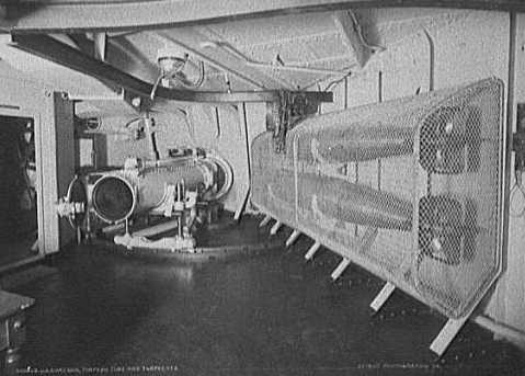
Photo 1. Underwater torpedo tube installed on the battleship USS Oregon [1]
In the case of submarines and battleships, fixed torpedo tubes with straight-running torpedoes running in the direction of the torpedo tube presented a serious tactical restriction. These vessels often were not free to maneuver to take up a convenient attack position.
When the torpedoes were equipped with gyro-setting gear that made possible setting the amount of turn after leaving the tube, the restriction mentioned above was removed. Then the torpedo could run in a direction different from the longitudinal axis of the torpedo tube. That means that the angle between the longitudinal axis of the torpedo tube and the sight line could be different from the angle between the torpedo course and sight line.
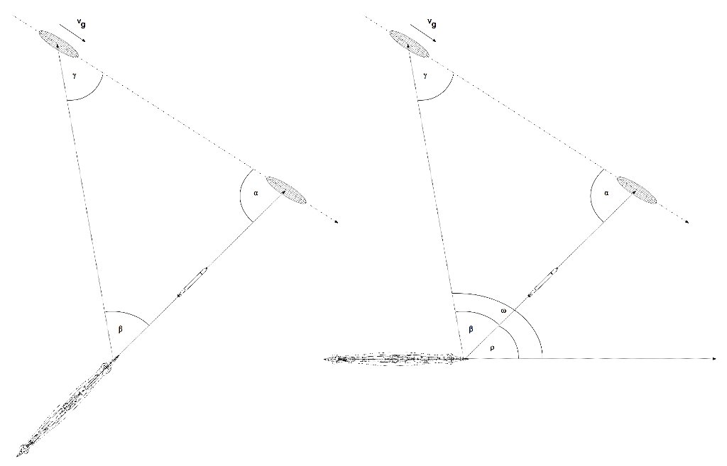
Drawing 2. Torpedo triangle for straight-running and for gyro-angled torpedoes
General relationships:
\[\begin{aligned} ρ = β ± ω \end{aligned} \]
where:
ρ - gyro angle (Germ. Schußwinkel) - angle between the torpedo course and the longitudinal axis of the torpedo tube.
β - deflection angle (Germ. Vorhaltwinkel) – angle between the sight line and the torpedo course.
ω - target bearing (Germ. Zielwinkel) - angle between the sight line and the longitudinal axis of the torpedo tube.
The first trials with gyro-angled torpedoes were conducted by the Americans at the beginning of the 20th century. When World War I broke out, most of the naval countries were in possession of such torpedoes.
The targeting of gyro-angled torpedoes is more complicated than the targeting of straight-runners due to the added distance and time they must travel because of the turn after firing. Aiming was also more complicated. The main problems are presented below based on a torpedo launch from the forward, starboard torpedo tube of the Helgoland class battleship - SMS Thüringen. SMS Thüringen was one of the first German dreadnoughts. She was armed with six fixed torpedo tubes located under the waterline. These tubes were located as follows: one tube was on the bow, a second on the stern – both in the longitudinal line of the ship. On each side of the ship two tubes were located – forward – just in front of first gun turret – and aft – just behind last gun turret. Both tubes in each pair were not parallel to the traverse line of the ship, but angled at 20°- forward in the case of forward tubes and aft in the case of aft tubes. The caliber of the tubes was 50 cm. The tubes were for G/7 type torpedoes: weight 1395 kg, length 7.020 m, range 4,000 m at a speed of 37 knots and 9,300 m at a speed of 27 knots, wet-heater, fueled by decalin, weight of explosives (hexanite): 195 kg.
Drawing 2. Helgoland class battleship SMS Ostfriesland with visible
openings of the starboard underwater torpedo tubes [2]
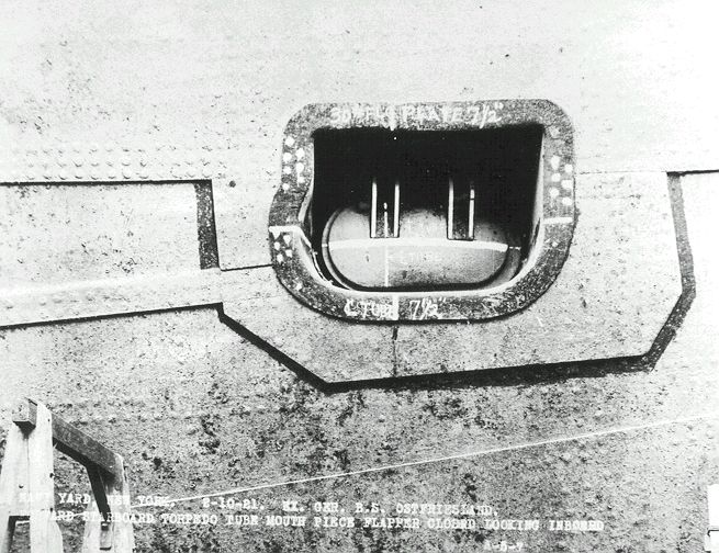
Photo 2. The muzzle door of the forward, starboard torpedo tube on the battleship SMS Ostfriesland [3]
One of the main problems appearing during firing from a side underwater torpedo tube of a cruising ship is that water streaming past the ship’s hull impacts the torpedo, which could lead to its damage or blocking in the tube.
This problem was partially solved by installing special bars which were extended from the ship’s hull before firing. These bars protected the torpedo from the water flow while it was leaving the tube. However, despite this solution, the speed of the firing vessel had to be reduced to about 15-20 knots.
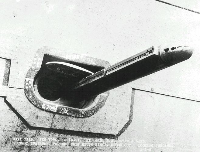
Photo 3. Extended bar from the forward, starboard side torpedo tube on the battleship SMS Ostfriesland [3]

Photo 4. Extended bar from the forward, starboard side torpedo tube on the battleship SMS Ostfriesland [3]
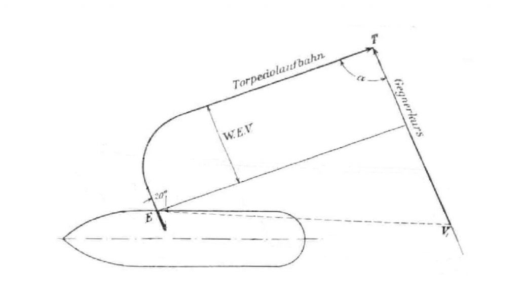
A torpedo after leaving the tube and before starting its turn, covered a distance called reach (Germ. gerade Vorlauf), which depended on the torpedo type (types C/06 and G/6 - 10 m, type G/7 - 15 m, type G7a and G7e – 9.5 m). Then it started its turn with a radius that also depended on the torpedo type (type C/06 - 145 m, type G/6 - 100 m, type G/7 - 105 m, type G7a and G7e - 95 m). After finishing its turn the torpedo ran straight toward the target. The angle between the torpedo run and the longitudinal line of the torpedo tube is the torpedo gyro angle entered into the gyro-setting gear of the torpedo. There is an offset between the line of the torpedo run and the line crossing the muzzle door of the tube that is called advance (Germ. Winkeleinsteuerungsversetzung). The amount of this offset is a function that depends on the reach and gyro angle.
When the gyro angle is 90º the following torpedoes have an advance equal to:
C/06: 155 m
G/6: 110 m
G/7: 120 m
G7a and G7e: 104,5 m
Because the length of the initial run (reach) is about 10% of the advance for a gyro angle of 90º, the advance for the gyro angle ρ can be approximated with formula:
\[\begin{aligned} V_{ρ} = V_{90} * (1 - cos ρ) \end{aligned} \]
where:
ρ - gyro angle
Vρ - advance for the gyro angle ρ
V90 - advance for the gyro angle of 90º, R+L (where L is reach, R is the radius of the torpedo turn)
Drawing 3. Advance as the result of torpedo turn [4]
If the advance was not included during torpedo aiming, the torpedo course would cross the target course at the distance:
\[\begin{aligned} d = \frac{V_{ρ}}{sin α} \end{aligned} \]
where:
α is the track angle
So the aiming point should be located at distance d in front of the target (on the target’s course line).
Another factor which complicates gyro-angled torpedo targeting is the fact that in the case of submarines and battleships, the torpedo director is not located at the torpedo tubes. So the additional parallax correction P (Germ. Winkelparalaxverbesserung) resulting from the offset between the torpedo director and the torpedo tubes has to be incorporated.
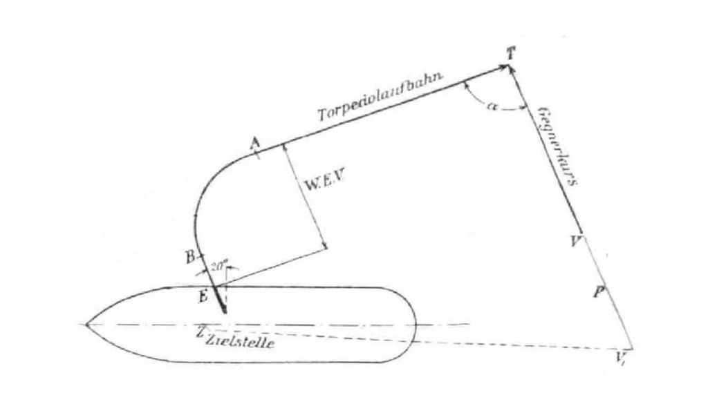
Drawing 4. Parallax resulting from the offset between the torpedo director and the torpedo tube [4]
This correction is calculated analytically on the basis of the so called equivalent point of fire E1 (Germ. ideeller Torpedoeintrittsort). This point is located on the backward extension of the torpedo run line at a distance equal to the sum of the length of reach and the length of the torpedo turn, measured from the point A – ending of the turn. In other words, the length of segment E1A is equal to the length of segment EA. The torpedo triangle is constructed using point E1. Knowing its position relative to the torpedo director, the correction P can be calculated. The position of point E1 is a function of gyro angle ρ.
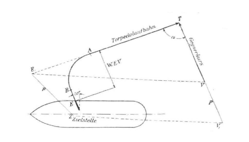
Drawing 5. Torpedo triangle constructed on the equivalent point of fire [4]
The described algorithm was quite complicated so before the invention of electro-mechanical fire control computers, tables were prepared which contained parallax corrections for arbitrary firing data.
The sample table for the forward, starboard torpedo tube of the battleship SMS Thüringen is presented in the drawing below.
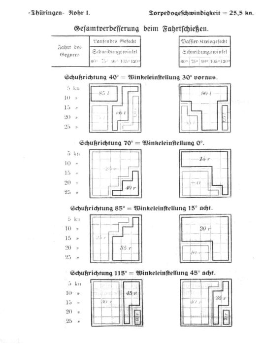
Drawing 6. Parallax correction table for the forward starboard
torpedo tube of the battleship SMS Thüringen [4]
It consists of two columns: one column contains corrections for the line of battle situation (laufendes Gefecht) and second – corrections for the "crossing the T" situation (Passier Kreisgefecht).
There are corrections for four settings of the gyro-angle (Winkeleinstellung): 30º port, 0º, 15º starboard, 45º starboard. That means the following offsets from the ship’s longitudinal line (Schußrichtung): 40º, 70º, 85º and 115º.
For each gyro-angle there is a small table where for a given target speed (Fahrt des Gengers) and track angle (Schneidungswinkel) the correction (in meters) can be found. The suffix 'l' or 'r' indicates, if the correction has to be applied in front or in back of the target.
The torpedo aiming and launching procedure for battleship underwater torpedo tubes was as follows: after initial determination of the target course parameters, the approximate torpedo course was calculated by means of a torpedo director. Then the appropriate torpedo tube was chosen and the gyro-angle setting was ordered that was the closest to the calculated torpedo course. From the appropriate table the parallax correction was read and the own ship course (in the range ~20º) was adjusted so that the set torpedo course was the same as calculated. Finally, the torpedo was launched at the moment when the target was at the distance from the aiming point equal to the value read from the corrections.
In the case of German U-Boats, the procedure was quite different. There only two gyro-settings were used (apart from the zero setting): 90º starboard and 90º port. The gyro-setting could be applied directly before the launch – when the torpedo was loaded into the tube and ready to fire.
A gyro-angled shot from the bow torpedo tubes was used only in the case where the U-Boat and the target were cruising in the same direction, while the shot from the stern tubes – when they were cruising in opposite directions. The commanders performed this kind of attack usually when the standard approach (with the zero gyro-setting) was not successful or was disturbed by an unexpected maneuver of the target.
If during a standard approach with the bow torpedo tubes the commander sees that he has gotten too close to the target, he can switch to a gyro-angled attack. He orders the 90º (starboard or port respectively) gyro-setting and at a distance of 200 meters from target, he changes the U-Boat’s course to be parallel to target. When the target gets to the traverse line of the U-Boat, the torpedo is launched.
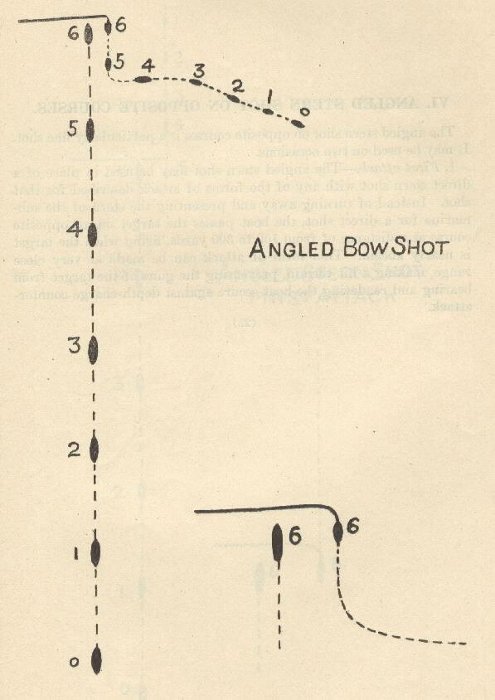
Drawing 7. [5]
A Gyro-angled shot from the stern torpedo tubes can be used instead of a standard attack from the stern torpedo tubes. In such a case rather than making a turn to a course perpendicular to the target’s course, the U-Boat cruises on a parallel course, but in the opposite direction. When the target gets to the traverse line of the U-Boat, the torpedo is launched.
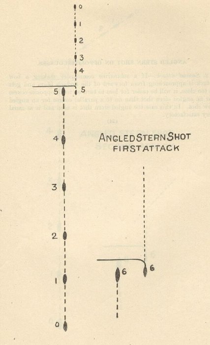
Drawing 8. [5]
When the U-Boat gets too close to the target during a bow approach, she can easily make a turn to the opposite course and fire from the stern torpedo tubes – similarly as in the previous case, the torpedo is launched when the target gets to the traverse line of the U-Boat.
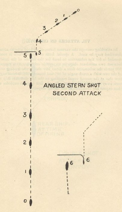
Drawing 9. [5]
In conclusion, it was technically possible to use gyro-angled torpedoes during the Great War.
Torpedoes were fitted with gyroscopes that allowed setting the angle of gyro-deviation and torpedo tubes were fitted with gyro-angle setting gear for entering the setting into the torpedo while the torpedo was in the tube.
The main reason that gyro-angled torpedoes were used very rarely was the complexity of the necessary calculations. The calculation of the parallax resulting from the torpedo turn after leaving the tube and from different locations of the aiming-device and torpedo tube was a complicated mathematical problem, difficult to solve without the use of electromechanical computing devices which only appeared a few years later.
Additionally, it was difficult to transfer the calculated values for the angle of deviation from the control room to the torpedo tubes. In those days it was done verbally and manually introduced to the torpedoes by crew members.
The whole process was time-consuming and prone to errors and distortions. During the dynamically changing tactical situation, a painstakingly calculated gyro angle was most often introduced into the torpedo too late to result in an accurate shot.
These problems were not solved until several years later when electromechanical torpedo calculators were introduced together with synchronizing links to transfer the gyro-angle to the torpedo and servos coupled with the gyro-angle setting gears inside the torpedo that continuously and accurately introduced the currently calculated gyro-angle. Until then gyro-angled torpedo attacks (except for relatively simple cases when the value of the gyro-angle was equal to 90°) were used rarely and were treated as a tactical curiosity.
References:
[1] United States of America Torpedoes Pre-World War II
[2] Schlachtschiffe - SMS Ostfriesland
[3] Schlachtschiffe - SMS Ostfriesland - Overall and Hull Detail Photos
[4] Handbuch des Torpedowesens, 1924
[5] German submarine attacks - ONI 44